Reschke, A.E. and Noppenberger, C.
Originally published 2011- 14th Australasian Tunnelling Conference
Brisbane Airport Link Earth Pressure Balance Machine
ABSTRACT
The Thiess John Holland Group is undertaking the design and construction of Brisbane’s Airport Link Project, the largest single investment in transportation infrastructure in Australian history. Twin Herrenknecht TBMs are being used to bore parallel road tunnels from Kalinga Part in Toombul through to Lutwyche, a distance of 2.45 km. At 12.48 m, these tunnel boring machines (TBM) are the largest diameter machines, outside of Japan, to incorporate annular two-component type grouting through the tailskins. Grout design, preparation and injection have been given particular attention in this project in order to push the boundaries of achievement. Laboratory testing was conducted on various mix designs to ensure the contract specifi cations for grout strength could be met. To study the mechanics of the grout injection process, Herrenknecht supplied a test rig which duplicates the grout injection systems on the TBMs. Multiple recipes were tested, carefully selected to balance the requirements of rapid strength development with high mobility (to completely fi ll the void between the segmental lining and the ground) and minimal bleed. Team Mixing Technologies, Canada, was selected as the grout plant provider based on the technical performance of their high shear colloidal mill mixers. Field results have shown that the colloidal mixer prepared grout gives almost double the strength of an identical grout prepared by a paddle mixer.
INTRODUCTION
At nearly $5 billion, the Brisbane Airport Link (APL) project sets the record as the largest single investment in transport infrastructure in Australian history and one of the most challenging engineering feats in Queensland history. The Thiess/John Holland group JV (TJH) is undertaking the design and construction of this megaproject which encompasses 25 bridges, nearly 15 km of tunneling and over 7 km of surface roadwork. When complete, it will produce the longest road tunnel in Australia at 6.7 km. Starting at Kalinga Park in Toombul, a pair of Herrenknecht tunnel boring machines (TBMs) are being used to drive the 2.45 km long twin bore sections of the 6.7 km road tunnel through to Lutwyche. At 12.48 m diameter and 4900 kW total installed main drive power these are the largest TBMs ever to be used in Australia. They are also the largest earth pressure balance machines (EPBMs), outside of Japan, where this method was first developed, to incorporate annular two-component type grouting through their tailskins (aka tail shields). Due to the record setting size of the tunnels, grout design and implementation were carefully studied. Team Mixing Technologies, Canada, was awarded the supply contract for the grout plant, largely based on the technical performance of their colloidal mixers which maximise grout strength and minimise minimal bleed. Field trials were undertaken with a Herrenknecht supplied grout injection test rig to realistically simulate the field behaviour of various mix designs. The mixes were selected to balance the requirements of rapid strength development with high mobility (to completely fi ll the void between the segmental lining and the ground). The performance requirements of the grout and initial results of the project grouting are discussed herein.
TWO COMPONENT GROUTING
TBM operations require the injection of material into the tail voids as the machine advances ahead of the segmental lining. Tail voids are created as the cutting diameter of the TBM has to be larger than the outer diameter of the concrete segments of the tunnel lining. Fundamentally, the two basic types of annular grout are thick, concrete like mortars and thin, mobile, two-component grouts. Although the Japanese pioneered the use of two-component grouts nearly 30 years ago, this method has only recently been widely adopted elsewhere and continues to gain popularity. Two-component type grouts are comprised of an ‘A’ component (usually a cement based grout with bentonite and a retarder/stabiliser) and a ‘B’ component accelerator (typically sodium silicate). They are thus often referred to as A/B type grouts. Two-component type grouts have a number of advantages over mortar type grouts.
- They have been shown to reduce the amount of absolute vertical ground settlement (Feddema et al, 2001) as compared to mortars and are being successfully used to control settlement when tunnelling through difficult ground in sensitive locations (Battye, 2010).
- Conventional mortar type grouts require high pressure concrete type pumps which can have a detrimental effect on the surrounding geology if excessive pressures are used. A/B type grouts are very fluid and easily pumped long distances from the surface to the TBM, simplifying the pumping arrangement. Because of the reduced viscosity of A/B grouts, they can penetrate the void space more effectively, with less energy, which also reduces the strain on the segmented linings (Robinson and Bragard, 2007). Smooth fl ow, positive displacement pumps can be used so control of pumping pressure is easily achieved.
- Use of a retarder/stabiliser can extend the shelf life of the ‘A’ component grout for several days, leading to less pipeline blockages and less wasted grout due to work stoppages or unforeseen delays).
- The early strength of the accelerated grout stabilises the ground and supports the liner almost immediately. Loading from the back up gantry wheels can be accommodated in a matter of hours. With some mortar grouts, the set time can be so slow that the tunnel lining can later move or distort (Robinson and Bragard, 2007).
- The grout material has low permeability, resists wash-out, and is very effective in sealing off underground water.
The biggest drawback to the two-component grout system is the level of sophistication required. The applied injection pressures and volumes of both the ‘A’ and ‘B’ components must be maintained and controlled during the injection process as the TBM advances. The injection pressure must be sufficient to fill the tail void completely but not so excessive as to cause leakage through the tail seals of the TBM. A high pressure water flushing system is also required to prevent clogging of the grout tube in the tail shield.
TUNNEL BORING MACHINES SPECIFICATIONS
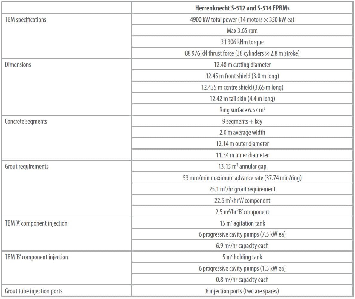
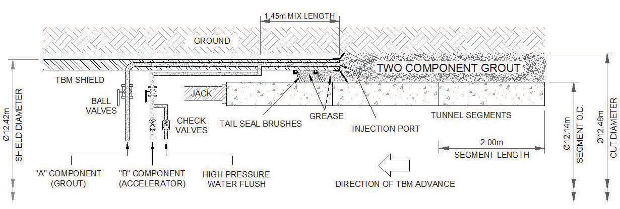
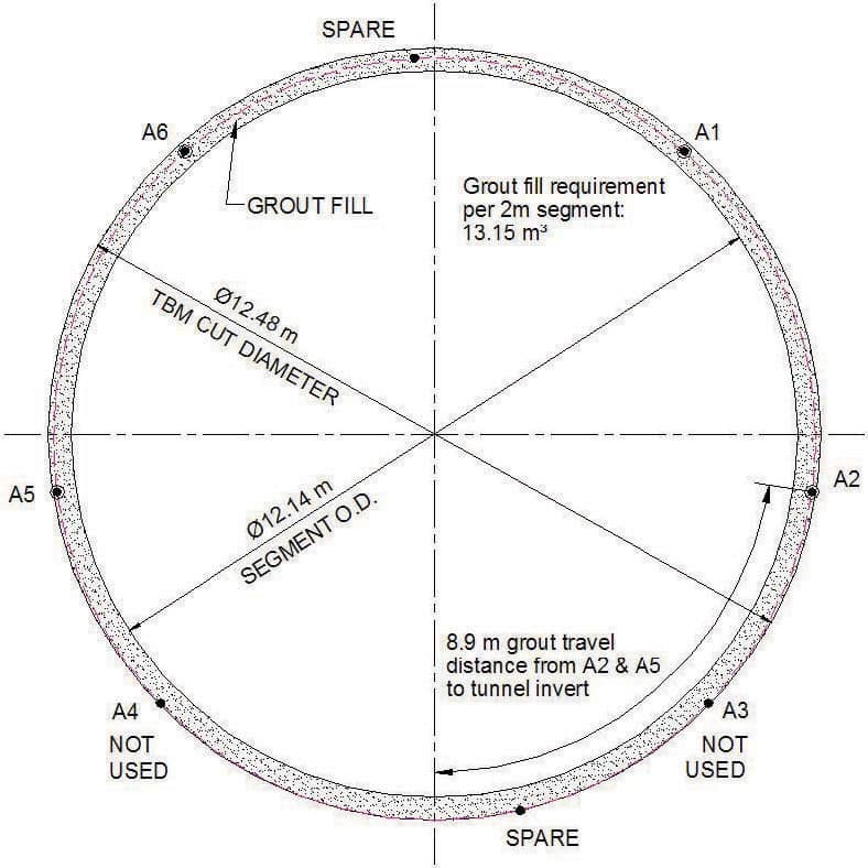
Details of the two Herrenknecht EPB machines are found in Table 1. Of particular note is the machine diameter of 12.48 m. These are the largest TBMs ever to be used in Australia. Equally impressive is the fact that, outside of Japan, these are also the largest EPBMs to use a two-component grout injected through the tail shields (mortar type grouts have been used on larger machines, eg 15.2 m diameter EPBM used on the M30 motorway in Madrid). A schematic of the tailskin injection system is shown in Figure 1. Accelerator is introduced to the grout tube via an injection box which is located 1.45 m from the end of the shield. Mixing occurs over this length before being discharged out the injection port. The TBM tailskin is equipped with a total of eight injection ports of which two as spares (Figure 2). However, only four are used in the primary annular grouting operations (A1, A2, A5 and A6). Thus, only four sets of pumps are used, leaving pump A3 for secondary grouting through the segmental liners and pump A4 as a spare. Pump A1 is also used to pump bentonite to the excavation chamber in the event of prolonged work stoppages.
GROUT PLANT DETAILS
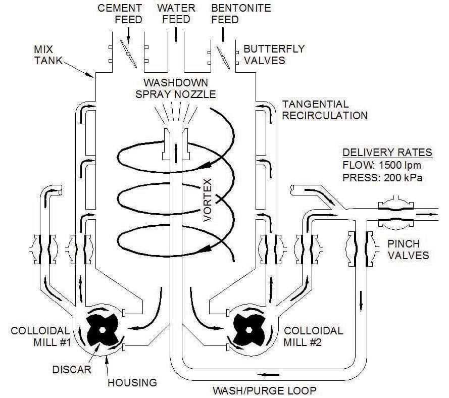
The key element to the surface plant is Team Mixing Technologies SD1350 colloidal mixer. Colloidal mixers have been in use in civil construction since 1937 and are widely recognised as the most efficient method of mixing cement based grouts (Houlsby, 1990). The colloidal mill houses a discar which spins at 2100 rpm (see Figure 3). The clearance between the discar and the walls of the housing is about 3 mm. It is here that violent turbulence and high shearing action is created which is capable of breaking down clusters of dry cement particles. The SD1350 houses two of these mills with a throughput of up to 750 L/min per mill.
The strong vortex action inside the tank rapidly assimilates the mix ingredients (cement, bentonite and stabiliser) into the mix water. The resulting slurry exhibits colloidal properties, ie the cement particles remain in suspension with minimal settling or bleed. The practical benefit, as compared to lower energy paddle type mixers, is not only reduced bleed but also increased strength (Reschke, 1998). Grout testing on this project has demonstrated that colloidal mixed grout yields virtually double the strength of the test mixes prepared by paddle mixers. Ultimately there is the potential for long term cement (and cost) savings over the life of the tunneling project as the recipe is fine tuned.
Within the grout plant, the colloidal mixer sits atop load cells and thus functions as a weigh batch system. Water is first weighed in using a fast feed piping system followed by a slow feed system to attain a high weigh accuracy (standard deviation <0.25 per cent of target weight). This water is circulated through the mixer and an internal spray nozzle to scour the mixer clean. This water remains in the mixer and is used for the subsequent batch of slurry.
The stabiliser is then dosed via a diaphragm pump and measured by a flow meter with a standard deviation less than 0.3 percent of target. Both bentonite and cement screw conveyors are controlled by frequency drives to accurately feed in the required quantities of material via fast then slow feed rates. Batch logs indicate a standard deviation of less than 1.0 per cent of target weight for the cement feed. Bentonite is added first and mixed for about 30 seconds before the cement is added. This is done to prehydrate the bentonite as much as possible. After the cement is added, mixing continues for an additional minute after which the batch is automatically transferred to the 3.2 m3 capacity agitation tank.
A 100 mm, 25 bar, Elepon peristaltic pump transfers the ‘A’ component grout to the 15 m3 capacity agitated holding tank on the TBM via a 100 mm diameter pipeline. Maximum pump output is 26.4 m3 /hr (at five bar) which equates to a 0.93 m/sec velocity though the pipeline. Based on site personnel’s experience this velocity should be acceptable to keep the cement particles in suspension and prevent settling and build-up in the line. Nevertheless, a pig launcher is also provided for the ‘A’ component line with pipeline pigging being conducted at least once per day.
A similar 42 mm peristaltic pump transfers the ‘B’ component (accelerator) to a 5 m3 holding tank on the TBM. Maximum pump throughput is 2.3 m3 /hr (at five bar). Pumping pressures for both lines are monitored by the plants PLC program and adjusted automatically in response to high pressures.
Communication between the surface plants and the TBM grout operator is achieved via the site’s fibre optic network. A control panel in the TBM allows the grout operator to either manually control the surface transfer pumps or automatically keep the TBM holding tanks full. Using ethernet/IP protocols, the site engineering office is also connected to the plants allowing for downloading of shift reports as well as real-time viewing of the plants human machine interface (HMI) screens.
REQUIRED GROUT PERFORMANCE
The Parsons Brinckerhoff Arup Joint Venture conducted the tunnel design and provided the contract specifications for the backfill annulus grout (Table 2). A grout strength of 1 MPa is specified when the segmental lining is loaded by the weight of the first backup gantry. Based on the TBM and gantry geometry and taking into account the average advance rate and ring build time, the first bogie wheels of the backup gantry will typically load the segments and grout from 12 to 24 hours after placement of the grout.
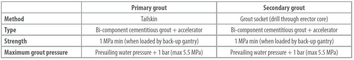
While the grout strength is of primary importance from the contract perspective, other properties of the grout are also important to ensure maximum void filling. These properties include working life, flowability (viscosity), stability (bleed) and gel time.
The ‘A’ component grout is prepared on surface then pumped to a holding tank on the TBM backup. While it is not uncommon to see two to three day grout storage life adopted and/or specified on other projects to accommodate unforeseen work stoppages a minimum shelf life of only 24 hours was deemed acceptable for this application.
Smaller diameter EPBMs typically utilise two injection ports at approximately the two and ten o’clock positions. However, due to the signifi cantly larger diameter of the APL tunnels, four injection ports are necessary (see Figure 2, ports A1, A2, A5 and A6 are used). The two-component grout must therefore travel around the circumference of the segments from ports A2 and A5 through to the invert of the cut, a distance of 8.9 m. It is therefore important that the grout remain mobile and fluid. For this reason a relatively low Marsh funnel time is desirable. This is primarily a function of the water:cement ratio. To a lesser degree it also depends on the bentonite quality and content as well as the quality of the mixing; high shear colloidal mixing results in lower viscosities as compared to lower energy paddle mixing. Based on previous experience, TJH personnel deemed Marsh funnel times of eight to 12 seconds to be an acceptable guideline.
Herrenknecht designed the injection system of the TBMs such that the ‘A’ and ‘B’ components mix over a length of 1.45 m through the tailskin before reaching the injection port (see Figure 1). Based on the grout injection pump rates, it takes about five to ten seconds for the accelerated grout to travel from the injection port to the tailskin void. As a result, the risk of blockage is thus reasonably high dictating the use of highly flowable grout with longer gel times. A soft gel would fill the annular gap, reduce the risk of line blockage and be relatively easy to wash out with high water pressure if they occur. Grout gel times of five to 20 seconds were deemed acceptable with the preference being towards the longer time.
Although agitation tanks are employed at the surface and on the TBM, the stability of the ‘A’ component has importance with respect to residency time in the pipeline. Bleed needs to be minimised to prevent cement particles from settling out and building up inside the pipeline. Cement can harden up inside the line, reducing the effective area and increasing required pump pressures. While this can be mitigated through the use of pipeline pigging it is still preferable to minimise the grout bleed from the onset. Bleeds are controlled through the use of bentonite and through the use of high shear colloidal mixing. With a total pump distance approaching 2.65 km, a bleed of less than five percent was deemed necessary.
Also important to the pumping distance is the overall viscosity of the ‘A’ component. Viscosity can have a significant impact on the pumping pressures. Lower viscosity, as indicated by lower Marsh funnel times, reduce the pressure and energy requirements to move the ‘A’ component underground. Preliminary calculations indicate the delivery pumps on surface will require a maximum of 16 bar pressure to transfer the grout through to the end of the tunnel. This includes pipeline pressure losses plus additional losses for the hose reel, fittings and a pipeline cleaning pig.
GROUT DESIGN TESTING
Initial testing of grout samples was conducted by TJH personnel and subsequently followed up by Condat, who was selected as the supplier of the stabiliser.
TJH Recipe Testing
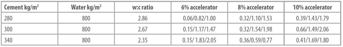
Grout testing was initially done on lab sized samples prepared with a paddle type mixer. A suite of tests were run varying the amount of cement per m3 of grout from 280 to 340 kg/m3 . Bentonite content was kept constant at 40 kg/m3 and the accelerator was varied from six to ten per cent of the total grout weight. The materials and suppliers were as follows: General Purpose (GP) cement from Sunstate Cement Ltd, Condat A Stabiliser L from Condat Lubrifi ants, Trugel bentonite from Unimin Australia (although in production Bentonil SCA bentonite from Sud-Chemie is being used) and NG sodium silicate from PQ Australia Pty Ltd. Results are shown in Table 3.
As expected the amount of accelerator has the greatest impact on the initial (ie one hour) strength with higher strengths achieved with higher dosing rates. However, the eight per cent and ten per cent accelerator dosing rates have only a marginally beneficial effect on the one and two day strengths as compared to the six per cent. Optimal dosing appears to be in the six to eight percent range.
Irrespective of the cement content the Marsh funnel times only ranged from 11 to 12 seconds. Bleed was negligible after one hour but ranged from four to 12 per cent after 24 hours. Based on the above results the 300 kg/m3 cement recipe (2.67 water:cement ratio by weight) was selected with eight per cent accelerator addition.
Well in advance of arrival of the TBMs and the grout plant, Herrenknecht supplied a test rig to the job site to accurately simulate the injection of the ‘A’ and ‘B’ components through the tailskin. The test set-up consists of an injection tube identical to that installed in the TBM’s tailskin but with a steel receiving tank to accept the grout (instead of the annular ring gap). The grout and accelerator are both delivered by progressing cavity pumps. Component ‘A’ is pumped through the oval opening in the injection bar whereas component ‘B’ fl ows through a hose to the injection plug in the simulated tailskin 1.45 m before the outlet port. The accelerator is added to the grout through an orifice in the injection box.
The ring gap is simulated by the connected steel tank which can be pressurised to simulate ground water conditions (limited to 3.5 bar). The pressure inside the tank can be adjusted during the injection process. Pressure measuring sensors and inductive fl ow meters indicate the current pressures and fl ow rates in injection lines A and B. All sensors are connected to a data logger.
Various recipes and conditions were simulated to prove the viability of the recipe, anticipated pressure conditions as well as confirm the design of injection system itself as it would be supplied on the TBM.
Condat Recipe Testing
Recognising the risk potential for blocking the injection ports, Condat undertook a series of recipe tests to try to optimise the performance of the grout. The targets they set out to achieve were:
- obtain a stable ‘A’ component grout (<5 per cent bleed) which is easily pumpable;
- maintain a soft gel (after accelerator added) to completely fi ll the annular gap, reduce the risk of line blockages and be easier to clean out with high pressure water in the event of a blockage;
- increase the gel time (by dilution of the accelerator); and
- retard the hydration for 24 hours.
Dilution of the accelerator decreases its viscosity making it easier to pump and easier to mix with the grout in the injection tube. This ensures a more homogenous mix is attained behind the segments.
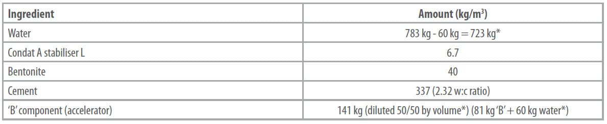
Condat utilised the same suppliers as per TJH testing. The parameters tested were as follows, water from 715 to 800 kg/m3, stabiliser from 1.25 to 9.1 kg/m3 , bentonite from 40 to 54 kg/m3, cement from 250 to 455 kg/m3 and accelerator from 81 to 108 kg/m3 as supplied and from 119 to 165.2 kg/ m3 diluted (50/50 by volume).
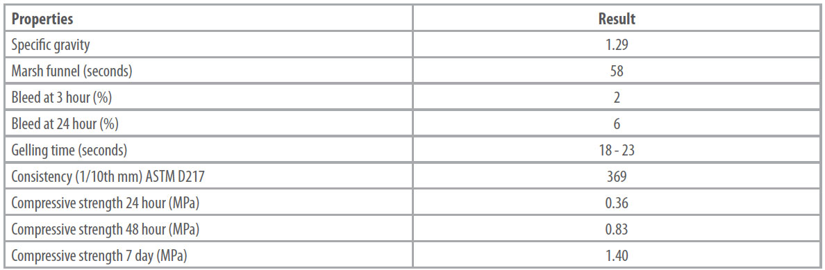
As expected, the grout strength correlated to the water:cement ratio of the grout (ie a lower w:c ratio grout has a higher strength). However, the short term strength also correlates with the amount of accelerator. The gel time was relatively immune to the parameter changes and only varied from 15 to 23 seconds. Bleed correlates to the amount of bentonite (more bentonite gives lower bleed) and the fluidity of the grout varied inversely with both the amount of bentonite and the amount of accelerator. Condat’s recommendations for the grout design are summarised in Table 4 and the properties are summarised in Table 5.
Condat’s recommendations were not adopted for several reasons. To dilute the accelerator on-site would require modifications to the accelerator pumping equipment including the addition of an additional positive displacement pump, motor starter, flow meter and programming. To bring in diluted accelerator from an outside source would literally double the freight costs.
Of paramount importance is the fact that Condat’s proposed grout strengths do not meet the contract specifications of 1 MPa when loaded by the backup gantry. A design change would require the approval of the tunnel owner and designers and need to be demonstrated in practice. Given that tunnelling is currently being successfully completed without this design, there is minimal impetus for change.
This raises an interesting engineering design issue though. Condat’s opinion is that the strength of the grout is of secondary importance. Strength, as per the contract, is specified as an unconfined compressive strength (UCS). However, the grout is actually confined in situ which implies triaxial testing is truly representative of the behaviour. The 1 MPa unconfined strength could be achieved with a much lower strength grout that has some confining pressure. It is the author’s opinion that this has merit and should be considered by future designers.
For Condat, the ability of the grout to flow and completely fill the annular gap is the primary consideration. This is achieved with the diluted accelerator which gives a longer gel time and a softer gel and the related benefits previously mentioned.
TUNNELLING RESULTS TO DATE
At the time of writing, S-514 (northbound tunnel) has advanced 140 rings (280 m) and S-512 (southbound tunnel) has advanced 90 rings (180 m).
TJH is understandably pleased with the results of the grouting program to date. Measurements of the tunnel segments inner diameter have shown less than 8 mm eccentricity. This is attributable to both the accuracy of the segments themselves, the low injection pressures required to fill the tailskin annulus and the rapid setting of the grout which quickly stabilises the segments.
As for secondary grouting, quality has improved since the onset of tunnelling. Although some initial rings have taken close to 2 m3 of secondary grout, most rings are now taking marginal amounts, some as low as 70 L.
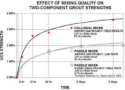
Daily testing of the grout is conducted for quality control purposes. The average results to date for both TBMs are shown in Figure 4 and compared to the initial lab results. Also shown are tests conducted by Tachibana Material Co Ltd (2008) for the Sydney desalination project tunnel for a virtually identical mix recipe using the same GP cement from Sunstate (and prepared with a paddle mixer). The results are virtually identical to TJH’s initial testing.
However, the daily production results for Team Mixing’s colloidal mixer based batch plant are showing virtually double the strength at any given time. This is a noteworthy difference and illustrates the superior mixing capabilities of the equipment. The 1 MPa required strength is actually being achieved in 2.5 to three hours. Consideration is now being given to reducing the cement content which, over the remainder of the tunnelling operations, could result in substantial cost savings to TJH.
Some minor improvements have been made to the grout injection system on the TBM. The type of check valve used for the accelerator and water flush lines has been changed and also increased in size. This has improved the reliability of the system and reduced blockages.
A number of procedural changes have been adopted as well. Accelerator injection is automatically stopped (via the injection PLC) when the thrust jacks are 100 mm from completing the push. This clears the grout tube of all accelerator. If the advance is stopped before completion of a full ring then a minimum of 9 L of grout (no accelerator) is also flushed through the grout tube (there is approximately 6 L of grout between the manual ball valve and the accelerator injection box and another 3 L from the accelerator injection box to the tailskin outlet). This is followed by ten seconds of high pressure water flushing (up to 200 bar).
For any work stoppages greater than five minutes (this includes ring builds and weekend shut downs) the grout and accelerator ball valves at the tail shield are closed (refer back to Figure 1). Also, grout lines and injection tubes not in use have to be filled completely with tail shield grease to avoid blockage from the rear.
CONCLUSION
With a 12.48 m cut diameter and 4900 kW of installed main drive power, the twin Airport Link Project TBMs are the largest machines ever to be used in Australia. They are also the largest EPBMs, outside of Japan, to incorporate annular two component type grouting through their tail shields.
Team Mixing Technologies has supported the Thiess John Holland JV with the supply of a project specific grout plant design which included twin surface grout plants, transfer pumps to the TBM and valves and controls on the TBM holding tanks. Underground and surface equipment communicate via the site fibre optic line which also links to the site engineering offices.
While tunnelling operations are still in the early stages, primary grouting operations are being conducted successfully with minimal segment eccentricity and acceptable quantities of secondary grouting. The grout itself, through the use of a high shear colloidal mixer, has exceeded performance expectations and has the potential to result in significant cement savings over the duration of the project while still maintaining the required contractual performance specifications.
As experience is being gained with the two-component grout and the four port injection requirement of this large TBM, confidence is growing that this project, while pushing the boundaries of achievement, will proceed satisfactorily through to completion of tunnelling in Lutwyche.
REFERENCES
Battye, G, 2010. Two part or not two part? Tunnelling Journal, June/July, pp 8-13.
Houlsby, A C, 1990. Construction and Design of Cement Grouting – A Guide to Grouting in Rock Formations, pp 10-28 (John Wiley & Sons: New York).
Reschke, A E, 1998. The development of colloidal mixer based CRF systems, in Proceedings Minefill ’98 (ed: M Bloss) pp 65-70 (The Australasian Institute of Mining and Metallurgy: Melbourne).
Robinson, B and Bragard, C, 2007. Los Angeles metro gold line eastside extension – Tunnel construction case history, in Proceedings Rapid Excavation and Tunneling Conference (ed: M Traylor and J Townsend), pp 472-494 (Society for Mining, Metallurgy and Exploration, Inc: Littleton).
Tachibana Material Co Ltd, 2008. Backfill grout mixture test results and proposal, Bluewater JV report, 9 April.