Reschke, A. E.
ABSTRACT
Optimized mine planning of the Leeville Gold Mine, Nevada, necessitated the requirement for an average of 2540 tpd of high quality cemented rockfill (CRF) in primary stoping blocks and underhand cut and fill workings. To meet this requirement, a number of innovative design features were incorporated into the overall batching plant design. Foremost is the use of a dedicated skip to transfer crushed aggregate from surface down through the ventilation shaft to twin underground storage silos. Also, the use of a high shear colloidal mixer on surface to pre-slurry a cement/flyash binder with pipeline delivery to one of two separate underground CRF mixing stations was incorporated. Finally, the binder and aggregate are combined in a 9 m3 twin shaft compulsory type mixer before loading into teleram trucks for placement.
INTRODUCTION
Newmont Mining Corporation’s Leeville Project consists of three distinct underground deposits referred to as the Four Corners, Turf and West Leeville. These deposits are all part of the famous Carlin trend, a large gold system extending northwest from the Carlin Mine, in Eureka County, Nevada. They are relatively deep, located approximately 425 to 640 m (1,400 to 2,100 ft) below surface. The orebodies are characterized as carbonaceous, sulphide refractory high-grade gold deposits (Jackson et al, 1998), with the ore being processed through the Carlin roaster.
The Leeville project is Newmont’s first shaft access mine in Nevada (all existing underground mines are ramp access from surface or through open pits). Initial development commenced in 2002 with the start of a 1.2 km (1 mile) decline from the Carlin East underground mine. This drift serves both as an exploration platform and as secondary access to the Leeville project.
In early 2003 sinking of both the production shaft and an adjacent ventilation shaft began. The production shaft was completed in 2006 to a depth of 571 m (1875 ft). The ventilation shaft, designed only to a depth of 443 m (1455 ft) was completed first allowing for actual production to begin in Q3 2005 with hoisting capabilities through this shaft. Production rates of 1900 tonnes (2100 tons) per day were attained by the end of 2006 officially giving the project commercial operation status.
As infrastructure continues to be put in place, production rates in the order of 2900 tonnes (3200 tons) per day should be achieved by the end of 2007. Annual gold production rates of between 12,400 and 14,000 kg (400,000 and 450,000 oz) per year are anticipated with a mine life of 7 years. The labor force consists of about 290 people.
As with other underground Nevada operations, mining methods employ both underhand cut and fill and longhole open stoping. The cemented rockfill (CRF) system provides the primary means of ground support and is a critical element in the mining cycle from both a safety aspect as well as for maximizing the extraction ratio of the highly valuable ore.
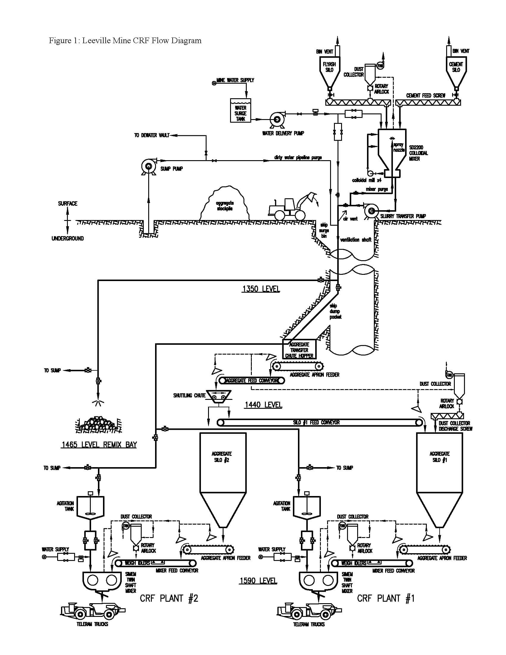
Team Mixing Technologies was awarded the design/build contract for the CRF batching plant which is currently under construction. However, to facilitate early mine production, the backfill system is being commissioned in stages. The surface slurry plant, see Figure 1, was put into operation in Q1 2006. Backfill plant #2 is expected to be operational in Q2 2007 with plant #1 to be operational a few months later.
At present, cementitious slurry (no flyash) is currently delivered underground through a 100mm (4”) pipe in the ventilation shaft down to the 1350 level and laterally out to the 1465 level remix bay. A 5.4 m3 (7 yd3) Normet transmixer carries the slurry to stoping areas where it is either added to run-of-mine development waste to produce fill for primary longhole stoping blocks, or added to a crushed aggregate for underhand cut and fill drifts. A scooptram is generally used for mixing purposes, yet, despite the relatively poor mixing of the slurry and the aggregate, strengths in excess of 3.5 MPa (500 psi) are readily achieved with the run-of-mine waste at 7% cement addition.
CRF DESIGN PARAMETERS
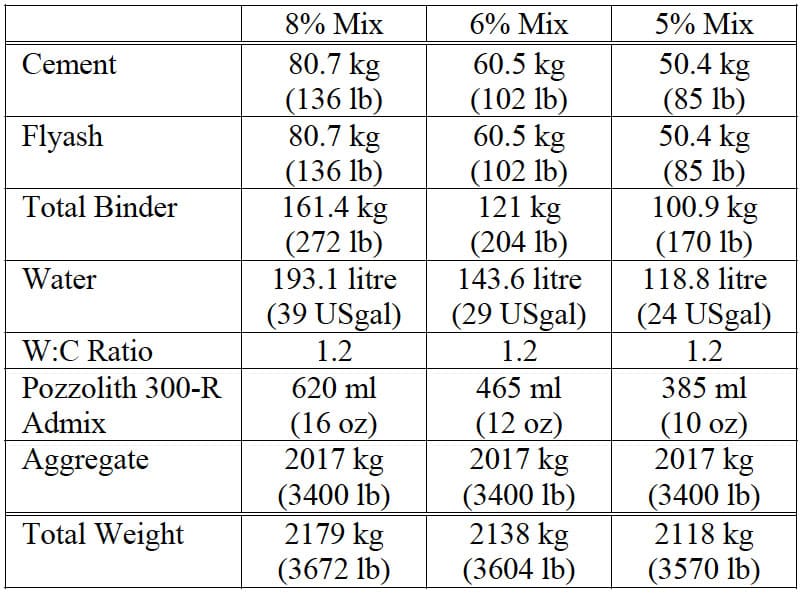
Table 1 gives the anticipated range of mix recipes for producing a cubic meter of backfill. The high strength mix (8% total binder) has a target strength of 6.9 MPa (1000 psi) which is appropriate for the underhand cut and fill stopes. All recipes call for a 1.2:1 water:binder ratio (by weight) which, based on previous experience at Newmont’s Nevada operations, yields optimal hydration of the rockfill. Experience also indicates that a 50:50 blend of Type II cement and Type C flyash yields a sufficiently good binder with significant cost savings versus straight cement.
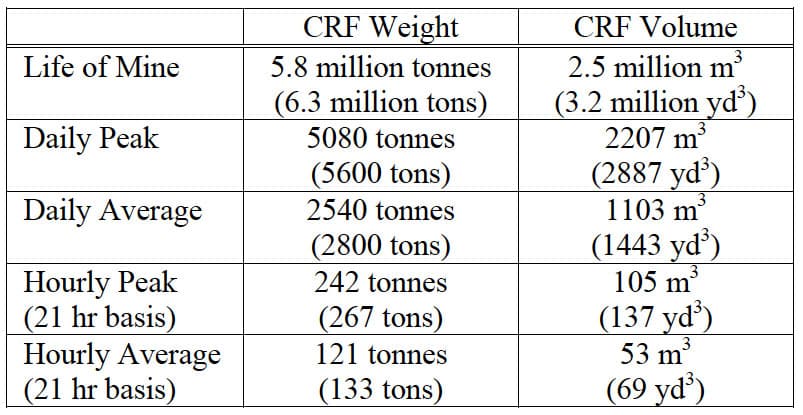
CRF plant throughput, based on projected mining rates, is indicated in Table 2. An effective 21 hour operational day was assumed in the calculations for hourly requirements.
CRF PLANT SURFACE EQUIPMENT
Colloidal Mixer
The key to the surface plant is Team Mixing Technologies SD2200 Tornado colloidal mixer. The use of colloidal mixers in the preparation of cemented rockfill was pioneered by Team Mixing in 1995 (then operating as Team Manufacturing Ltd.). Since that time, the benefits and advantages of colloidal mixer use have gained wider acceptance. Colloidal mixers can now be found in CRF and paste fill plants in North and South America as well as Europe.
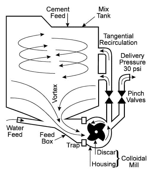
Colloidal mixers have been in use in civil construction since 1937 and are widely recognized as the most efficient method of mixing cement based grouts (Houlsby, 1990). The colloidal mill (see Figure 2) houses a discar which spins at 2000 rpm. The clearance between the discar and the walls of the housing is about 3 mm (1/8”). It is here that a violent turbulence and high shearing action is created which is capable of breaking down clusters of dry cement particles. The SD2200 houses 4 of these mills each with a throughput of up to 850 l/min (225 USgpm).
The most practical benefits of the colloidal mixers with regards to backfill production are:
- speed of mixing,
- increased slurry strength, and
- reduced dust generation.
The strong vortex action inside the tank rapidly assimilates the mix ingredients (cement, flyash, and admixtures) in as little as 2 minutes. The resultant slurry exhibits colloidal properties, i.e. the cement particles remain in suspension with minimal settling or bleed.
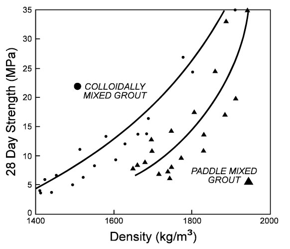
Colloidal mixers are clearly superior to paddle type mixers in the preparation of slurries for CRF (Reschke, 1998). As per Figure 3, higher strengths can be attained by virtue of the quality of the mixing of the cement and the water. Ultimately this should provide for long term cement (and cost) savings for the operation.
The surface plant incorporates a dust collection system which scavenges dust from the colloidal mixer when the dry ingredients are added. Newmont’s Deep Post Mine pneumatically conveys dry cement powder underground to a storage bin before feeding into a twin shaft backfill mixer. Due to problems with dust arising from this part of the system, Newmont wanted to avoid this with Leeville and consequently decided to go with a surface based slurry mixer.
The colloidal mixer is situated atop load cells and thus functions as a weigh batch system. Water is first weighed in using a fast feed piping system followed by a slow feed system to attain a weigh accuracy of ±0.5%. This water is circulated through the mixer and an internal spray nozzle to scour the mixer clean. At the end of shift this water would be directed to a sump, however, in most cases it remains in the mixer and is used for the subsequent batch of slurry.
Cement is fed in by a screw conveyor which is jogged if necessary to also attain a weighing accuracy of ±0.5%. Flyash will follow in a similar manner when the plant is completed.
After mixing is complete the slurry batch is sent underground through a 100 mm (4”) line down the ventilation shaft to a diverter valve on the 1350 level. At present, the slurry is only redirected through lateral development to the 1465 remix bay (or to an adjacent sump). When the underground mixer stations become operational the diverter valve will predominantly direct the slurry through to the 1440 level and on to the individual mixer stations.
Surface Silos
Both the cement and the flyash storage silos have 200 tonne (225 ton) capacities. Bin vents are used for dust suppression when filling.
Aggregate Handling
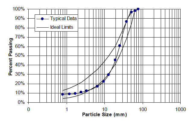
Aggregate for the CRF system is sourced from a nearby quarry which also produces material for the Deep Post, Deep Star and Carlin East mines. Aggregate is comprised of a calc-silicate (Blue Star Island) limestone and is crushed at the North Area, near Newmont’s Genesis pit, to a -75 mm (-3”) size. Figure 4 shows a typical gradation curve. The ideal limits are based on consultant recommendations (Minefill Services Inc., 2005).
In the interim, the aggregate is transported underground to Leeville through the Carlin East mine access decline. However, once the CRF plant is fully operational this material will simply be stockpiled near the Leeville Mine ventilation shaft. A front end loader will then haul the aggregate to a 180 tonne (200 ton) surge bin at the ventilation shaft collar. The shaft is equipped with a pair of 9 tonne (10 ton) skips which hoist the aggregate to the 1350 level dump pocket.
CRF PLANT UNDERGROUND EQUIPMENT
Aggregate Handling System
The 1350 level dump pocket in the ventilation shaft has a nominal capacity of 385 tonnes (425 tons). The dump pocket discharges into a short (about 6 m or 20 ft) lined raise that transfers flow down to the 1440 level. Aggregate levels in the dump pocket are monitored by a laser level. All hoisting functions are controlled or assisted by the ventilation shaft PLC.
The transfer raise connects to a chute which charges a 380 tonne (420 ton) per hour apron feeder. A 1.2 m (48”) wide belt conveyor then moves the aggregate to a shuttling chute overtop a 4.9 m (16 ft) diameter, 910 tonne (1000 ton) storage silo (for backfill plant #2). The shuttling chute will either direct the aggregate into this silo or onto a 0.9 m (36”) wide conveyor which feeds an identical storage silo for backfill plant #1.
The 1440 level aggregate dust collection system, typical of most underground systems, consists of a pulse-jet dust collector, a 110 m3/min (3900 cfm) fan, airlock feeder and discharge screw. Fugitive dust is collected at the apron feeder and from both conveyor discharge points. This system runs automatically and has delayed shutdowns for fan and pulse-jets to help minimize dust.
Dust will be recycled back into silo #1 via the rotary airlock and a 23 cm (9”) diameter screw conveyor. The airlock and screw will run for a set amount of time during each aggregate feed cycle (typically 10 seconds).
1590 Level Aggregate Handling System
The base of the aggregate storage silos is accessed from the 1590 level. Here, each of these silos transitions to an expanding flow hopper, chisel shaped with 76o sides and a 0.9 x 3.6 m (3’ x 12’) opening size. The hoppers feed respective apron feeders with 910 tonne (1000 ton) per hour capacities. Each apron feeder discharges onto a 1.2 m (48”) wide belt conveyor (equipped with weigh idlers) to feed their respective backfill mixers.
Each backfill plant has its own dust collection system with 110 m3/min (3900 cfm) fan. The systems are similar to that on the 1440 level with the exception that the rotary airlocks discharge directly onto the belt conveyor when operating. Dust is scavenged from the silo discharge hopper, the apron feeder headchute and the belt conveyor headchute leading into the mixer station.
Slurry Distribution System
Pneumatic pinch valves are used to direct slurry to the appropriate locations underground. The first set of valves is located in the ventilation shaft at the 1350 level. Slurry is either directed laterally to the 1465 level remix bay (further valving directs flush water to a nearby sump) or down through the short aggregate transfer raise to the 1440 level.
On the 1440 level the line splits into two, again using pneumatic pinch valves to control flow direction. The slurry piping continues on the 1440 level and then down boreholes to 4500 liter (1200 USgal) agitation tanks situated atop each of the two 1590 level backfill stations. Additional pinch valves are used to divert slurry pipeline flush water into sumps at the mixer stations.
Backfill Mixing Plants
The two backfill mixing plants are virtually identical in layout, equipment type and capacity. Each houses a Simem MSO 9000Q twin shaft mixer powered by four 56 kW (75 hp) motors. The mixers are elevated providing full drive-through access for the haul trucks. Overhead bridge cranes are included to facilitate maintenance and repair. The dust collectors and slurry agitation tanks are also situated at the mixer stations.
BACKFILL MIXER STUDY
Purpose
Due to the need for a consistent and high quality CRF, particularly in underhand cut and fill stopes, a mixer is deemed necessary to ensure all rockfill particles are adequately coated with cementitious slurry. Newmont’s Deep Post Mine incorporates a Simem twin shaft mixer into its backfill system. Conversely, Newmont’s Deep Star Mine uses a Besser single shaft ribbon type mixer. In engineering the Leeville CRF facility, Team Mixing Technologies conducted a study on these two mixers to determine which was more suitable for the application taking into terms capital and maintenance costs as well as technical and operational factors. Other types of mixers were not considered in an effort to standardize as much as possible on components and critical spares.
Suitability
The Besser mixers have lower power requirements and are simpler in construction which is reflected in maintenance costs, USD $0.38/ton at Deep Star vs. USD $0.43/ton for the Simem at Deep Post.
The Simem mixers however offer more aggressive mixing (and thus reduced mix times), as well as an optional internal pressure wash system which reduces the necessary daily cleaning needs of the mixer and thus provides some long term labor savings.
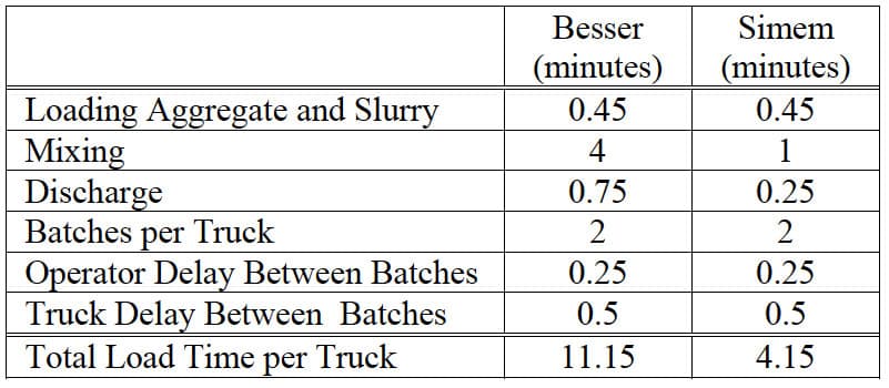
The truck fleet consists of 18 tonne (20 ton) and 28 tonne (31 ton) teleram trucks. With a zero slump rockfill the Besser mixer can batch 6.9 m3 (9 yd3) versus the Simem at 6.1 m3 (8 yd3). However, because the trucks have a larger capacity than the batching size of the mixers, double batches are required. Batching times thus become critical and are reflected in Table 3.
Taking into account the average truck size, the need for double batches and the load time per truck, the Besser mixer will output 1310 tonnes (1440 tons) per day whereas the Simem mixer will output 3520 tonnes (3880 tons) per day.
With the average backfill requirement previously shown in Table 2, two Besser mixers would be needed in place of a single Simem mixer. If the peak fill requirements are to be met then either four Besser mixers or two Simem mixers would be required.
Ultimately the use of two Simem mixers was approved to ensure that peak CRF production needs will be met. Some redundancy is also provided as one plant alone can handle the average daily production requirements. Repairs and maintenance can be accomplished on the second plant without adversely affecting the overall backfill throughput.
CRF PLANT CONTROL SYSTEM
Overall Summary
The CRF system is designed to automatically deliver backfill underground to Teleram trucks on demand. Cement and flyash are blended with water in a colloidal mixing system on surface. A slurry transfer pump feeds the slurry to the underground piping system where the slurry is staged in agitation tanks above the underground mixers.
Aggregate is prepared on surface and transported underground via skip hoist to the aggregate transfer chute. A material handling system consisting of an apron feeder, diverter chute, and conveyor belts transports aggregate to two large storage silos used to supply backfill plants #1 and #2.
At the backfill plants, the appropriate quantities of aggregate, slurry and additional make-up are loaded into the mixer virtually simultaneously. Aggregate is fed to the respective mixer via an apron feeder and a belt conveyor with weigh scale. The agitation tanks, atop load cells, feed slurry into the mixer by loss-in-weight. Water, in addition to that present in the slurry, is fed directly to the mixers using slow and fast feed valves on a pressurized line. Magflow meters are used to measure the water. Once fully charged, the mixer will mix for a set amount of time. The finished backfill batches, varying in size and formulation are then discharged to haul trucks.
Control Room
The main control room is located underground near backfill mixing plant #2. The entire backfill system including the surface plant can be monitored and controlled from this location via a single human machine interface (HMI). The surface plant, as it was commissioned ahead of the underground backfill mixers, has its own PLC and HMI touchscreen, but may only be used to monitor and control the slurry plant.
Each backfill plant also has its own independent PLC. All three plant PLC’s are connected to the HMI via an MB+ to Ethernet converter. This provides an independent communication path from the HMI to each PLC. The HMI computer can also be connected to the mine’s LAN via a USB adapter for transferring reports and other information. This provides isolation between the control network and the business network.
Operator Interface
There are two control stations (HMI’s) in the control room. Redundancy is built into the system as each station can be used to control one or both of the backfill plants.
A mouse is used to activate menu functions on the flat screen panels (a keyboard is not required). The entire backfill system can be monitored and controlled through a series of dedicated menu pages for each of the following areas:
- the slurry plant,
- 1440 level,
- 1590 level plant #1,
- 1590 level plant #2, and
- an overview page that provides a view of the most pertinent information from all areas.
A menu tab allows for quick navigation between these five main pages.
The operator interface provides indications of all active functions and alarm conditions. It also includes a recipe management interface and access to all tunable equipment parameters. The five main pages contain everything needed for system operation and monitoring. A variety of pop-up windows are accessible from the main pages and are used for modifying set points, for advanced diagnostics, and for other secondary features.
Backfill Batch Cycle
A typical batch cycle consists of three main steps: proportioning & loading, mixing and discharging. The operator initiates the batch cycle via the HMI. Provided there are no alarms and the system is ready, there will be a startup warning and the mixer paddles will start. The paddles remain running as the system continues through the entire batch cycle.
During loading, preset quantities of each ingredient are fed into the mixer. Slurry and water feed only begin after a set amount of aggregate has been added to the mixer. This set point is different for the slurry and water thus allowing these feeds to be staggered. A set amount of water is reserved for cleaning the line after the slurry feed is complete. If slurry feed is not completed in time, water feed will shut off at the reserved amount before the target and resume feeding after the slurry has finished. The hold/reset button on the HMI screen may be used to pause or cancel the batch cycle. If switched to hold, all feeds to the mixer will be paused as the mixer continues running.
Once the mixer is fully charged, the mix cycle begins. This is simply a timed mixing period where all ingredients are combined to produce the backfill. When complete, the HMI and discharge light will indicate the mix is ready. The operator starts the timed discharge cycle by clicking on the discharge button. A warning signal occurs prior to the mixer gate opening. Following discharge, the gate closes leaving the mixer running for successive batches. After a preset idle period, the mixer will eventually shut down. Should an extended delay occur prior to discharge, a warning will remind the operator that the mix is ready. Finally, further alarms will indicate that the mix must be discharged or otherwise discarded.
Backfill Mixer Wash Cycle
The Simem mixers have an auto-wash cycle which utilizes two high-pressure water pumps, stepping through four wash valves in sequence (the timing is operator adjustable). A pre-set amount of water is also fed into the mixer from the main water line at the start of the wash cycle. This helps clean the line and feed nozzles in the mixer. The wash cycle can be cancelled should batching again be necessary. After the wash sequence is complete, the discharge light will begin blinking. This button must be clicked to initiate discharge, after which the discharge alarm will sound and the gate will open.
If manual mixer washing is desired, a “Hand Wash” button at the mixer may be used to start a water pump which operates a water lance. Typical of most push button functions, the “Hand Wash” button acts as a toggle and can be pressed again to deactivate. The hand wash function can not be used if an auto wash cycle is in progress. The frequency of wash cycles is left to the discretion of the operator, however these are always performed at the end of a shift. Wash prompts are displayed automatically as necessary.
Backfill Recipe
The recipe for the mixer specifies the total mix weight and the percent of each raw material (aggregate, binder, and water) by weight. These percentages are used to calculate the raw material target weights that are then converted to target feed amounts of aggregate, slurry, and water. The known water/cement (or water/binder) ratio of the slurry in the agitank is used to determine how much slurry and water are needed.
If the specified batch size is greater than the mixer capacity or if the specified aggregate weight exceeds the mixer limit, two half-mixes will automatically be called. The second half-mix will start automatically following mixer discharge. However, the discharge function must still be used to initiate both discharge cycles of the double batch.
When the operator initiates a backfill batch, an HMI pop-up prompts the operator for the truck number and mine heading. This is one of the few times when the keyboard is actually required. Batching will not begin until the ‘OK’ button is clicked. Onus is on the operator to select the proper recipe and batch size prior to batching, otherwise the system defaults to the previous batch recipe. Recipes may be selected from a pull-down list and may be edited within a separate, password-protected window.
The truck number and mine heading, along with the time, date, and active recipe information is included in the batch report. The batch report also includes target and actual feed amounts (aggregate, slurry, and water), and the breakdown amounts of each slurry ingredient (water, cement, flyash and additives).
Aggregate Handling
Aggregate apron feeders and conveyor belts on all levels have audible/visual startup alarms similar to the backfill mixers. Interlocks assure that all downstream devices are confirmed running prior to operating any conveying device. Side-travel and plugged-chute sensors are also utilized to prevent material spillage.
Each backfill plant uses a conveyor scale to govern the aggregate quantity fed to the mixer, shutting off the apron feeder and conveyor belt as necessary. Typically, the weigh-conveyor will be left loaded with material. Alternately, the weigh-conveyor may be left empty for maintenance, taring or calibration. In this mode, the apron feeder will stop based on measured and estimated material on the conveyor. This estimate portion is calculated using the feed rate detected by the conveyor scale. The conveyor will continue running until empty. An alarm will indicate if the actual feed amount is not within the set limits. This feature disables after the conveyor has been emptied since it is designed to be used on the last batch only.
Agitation Tank Slurry
The agitation tanks are used to stage slurry above the backfill mixers. Above each agitank is a pair of diverter valves that will divert material from surface to the agitank or to the sump. To prevent unwanted material from reaching the agitank between batches, or when flushing, the default position for these valves is to the sump. Below each tank is a single discharge valve for gravity feed to the backfill mixer. Feed in and out of the agitank may not occur simultaneously and is interlocked. If underway, the surface feed cannot be interrupted and is given priority. Subtractive slurry feed to the mixer is via a two-stage, i.e. fast and slow, piping arrangement as the flow rate varies with agitank levels.
Backfill batches are inhibited if there is insufficient slurry in the agitank for a full batch, including a double batch when dictated. The agitators run continuously above a pre-set level to minimize splashing. When agitank fill is enabled, the tank will automatically replenish at the set-point level (unless mixer feed is underway).
There is a separate slurry recipe for each agitank that is used by the slurry plant when making a batch earmarked for that tank. The system tracks the amount of slurry and water supplied from surface and compares it with the agitank scales, alarming when necessary. Agitank content, based on the inherent recipe, is used for calculating slurry and water quantities for the backfill mixer.
Warning and dump alarms will initiate when agitank retention time has expired. These timers are reset each time a slurry batch is added to the tank. Purge (wash) water from surface may be diverted above the agitanks to sumps or may be sent through the agitanks to the backfill mixers for cleaning at the end of a shift.
Water
Water feed to the mixer is controlled by fast and slow feed valves on a pressurized water line. A Mag-flow meter totalizes this flow. Typically, feed begins with both valves opening. When the water feed reaches the slow setpoint, the fast valve closes. When the final water target point is reached the slow water valve closes.
Aggregate Silo Fill (1440 Level)
Material handling equipment on the 1440 level is used to convey aggregate from the skip transfer chute to the two aggregate storage silos. When enabled, feed to these silos is automatic based on the silos laser level set points. Standard startup alarms and interlocks are utilized. All conveyor belts run empty following aggregate transfer. When the system is active, and the material level is low in the aggregate transfer chute, a signal is sent to the surface to call for more aggregate. If the aggregate chute runs empty and is not refilled in time, the system will alarm and shut down.
Slurry Diverter Valves
A series of pneumatic pinch valves are used to divert slurry from the surface plant to the appropriate underground area or sump. The valves will only change position when the line is inactive. The exception to this rule would occur if power or air pressure is lost. When air pressure is lost, all valves will open. When power is lost, the valves maintain their position with the exception of the 1350 level valves which will divert to their default positions (open to backfill plants).
Alarms
If all alarms are clear and a new alarm occurs the ‘Alarm Clear’ button light will begin flashing and the general alarm horn and strobe is activated. Clicking the “Alarm Clear” button acknowledges the alarms and turns off the alarm horn and strobe, also changing the button light from flashing to solid. This indicates the alarms have been acknowledged, and once addressed, may be cleared by clicking again. If new alarms occur before the others have been cleared they will not trigger the alarm horn/strobe again but will display on the HMI.
CONCLUSION
The Leeville Mine CRF batching system is one of the more innovative backfill systems Team Mixing Technologies Inc. has designed and built to date. The surface slurry plant, multiple levels of aggregate handling equipment and twin backfill mixer stations have all been designed for single operator control with a high degree of reliability. When fully constructed the system will have the capacity to generate some 5080 tonnes (5600 tons) per day of high quality cemented rockfill.
REFERENCES
HOULSBY, A.C., 1990. Construction and Design of Cement Grouting – A Guide to Grouting in Rock Foundations, pp 10- 28 (John Wiley & Sons: New York).
JACKSON, M., LANE, M. and LEACH, B., 1998. Geology of the West Leeville Deposit. Guidebook 28: Carlin-Type Gold Deposits Field Conference Reprint 1998 Edition (Ed’s: Vikre, P., Thompson, TB, Bettles, K., Christensen, O., Parratt, R (Society of Economic Geologists: USA).
MINEFILL SERVICES INC., 2005. Carlin Backfill Aggregate QA/QC Guide. Report to Newmont Mining Corp. File #NMC-01.
RESCHKE, A.E., 1998. The Development of Colloidal Mixer Based CRF Systems. MINEFILL 98, (Ed: Dr M Bloss), pp 65-70 (AIMM: Carlton, Australia).