Originally published in North American Tunneling
Phil Antunes – Team Mixing Technologies, Abbotsford, British Columbia
ABSTRACT
Despite the recent rise in popularity of two-component grouts for annular space grouting, there is a lack of standards and procedures on how to test two-component grouts for the specifications required by tunnel engineers. This leaves open for interpretation appropriate testing procedures which presents a problem particularly in quantifying the early strengths frequently required by designers. A recent survey of several tunnelling contractors showed that each had developed and adopted procedures unique to their establishment. The objective of this paper is to propose a standard and procedure for determining the early strengths of two- component grouts and other general properties.
INTRODUCTION
In soft ground tunnelling operations, tail voids are created as the TBM advances ahead of the segmental lining. These tail voids result from the cutting diam- eter of the TBM being larger than the outer diameter of the concrete segments. In order to stabilize the segments and reduce ground settlement, this annular space needs to be filled as the TBM advances.
There are two basic types of annular grouts currently in use: thick mortar type grouts and highly mobile two-component grouts. Two-component grouts consist of an A and B component and are also referred to as Bi-Component or A/B Type grouts. The A-Component is a stabilized grout containing varied combinations of water, binders, bentonite (usually), and admixtures. The B-Component is a liquid accelerator that is added to the A-Component as it is being injected into the annulus.
As two-component type grouts have a number of advantages over mortar type grouts (Feddema et al., 2001, Peila et al. 2011; and Pellegrini and Perruzza 2009), they continue to gain in popularity. Consequently, industry standards need to be established to properly evaluate and the performance of these grouts.
TESTING PARAMETERS
As the A-Component is typically pumped from the surface grout plant to the TBM, several mix proper- ties need to be considered to allow the stabilized and then accelerated grout to be effective. These include:
- Flowability and viscosity
- Bleed and segregation
- Stabilization time
- Gel Time
- Compressive strengths
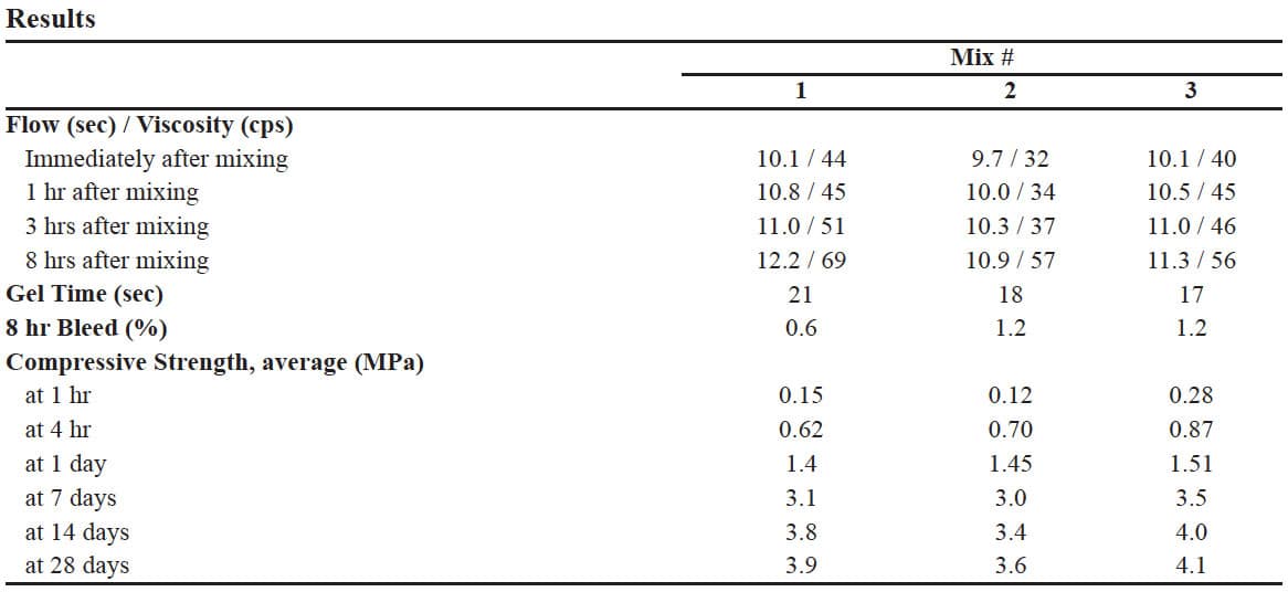
For the purpose of proposing a guideline for the development and testing of Two-Component mix designs, ASTM standards have been referenced for the following procedures. It should also be noted that any mix results given in this paper were done using a high shear colloidal mixer with raw materials avail- able locally to the author. Mix properties may vary substantially based on mix quality and ingredients (Reschke 2011). Table 1 shows the mix designs used for this paper.
Flowability and Viscosity
The flowability of the A-Component is important to predict pumping requirements and pipeline specifications. Higher flowability is advantageous as it implies lower pump and pipeline pressures as well as lower power consumption. Flowability is affected by:
- Water to cement ratio (W:C)
- Solids content and whether bentonite is used
- Admixtures
- The time since the retarder was initiated
Flowability is measured using a flow cone as per ASTM C939–10. However, two points in this standard must be noted:
- Bullet 7.6 of C939 requires mixing per ASTM C938 with a specified grout mixer. In order to gauge material flow it is recommended that a mixer be used that will accurately replicate the mixer that will be used for the project. Tests have shown that a mix prepared in a high-shear colloidal mixer for 1 minute had a flowability of 10.5 seconds while the same mix prepared in a standard lab Hobart mixer for 3 minutes required 16.5 seconds.
- Depending on the pot life required of the sta- bilized grout, flowability per ASTM C939 is repeated in intervals that will indicate the flu- idity of the grout as it ages.
Though flowability and viscosity are related, one cannot directly indicate the other. It is beneficial to parallel flowability readings with viscosity, using a viscometer, as these can be used to calculate pump requirements and head losses in the pipe network.
Bleed and Segregation
The conveyance line delivering the A-Component from the surface plant to the TBM is critical to the advance of the TBM. Grout bleed can lead to accumulations in the pipe invert that will reduce the cross sectional area of the pipe. This leads to higher pumping pressures, lower flow rates, and may ultimately completely occlude the pipe.
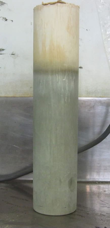
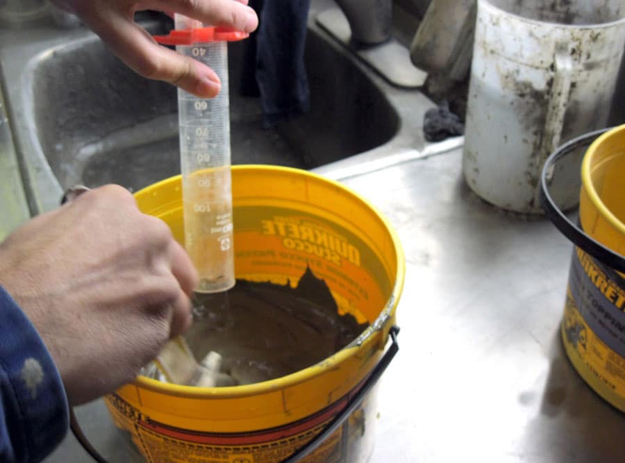
Testing for bleed also provides the opportunity to verify that no segregation internal to the grout is occurring. It has been noted that some anti-segregation admixtures at low water/cement ratios produced little bleed water, < 2%, but still segregated internally (Figure 1). It is beneficial to allow the sample to cure within the graduated cylinder for later inspection.
Stabilizer/Retarder
While chemically a stabilizer and a retarder react differently, the terminology is often used interchangeably. It is important to establish how long the A-Component will be held dormant before the injection with the B-Component. If more retarder is added than needed, it will increase the cost of the mix and require a larger dosage of accelerator to start the rapid set. The larger amount of accelerator also adds cost and may reduce the final compressive strength of the grout.
Though there are some modified tests to deter- mine the “pot life” of a mix, it is most practical to test the effect of the retarder with the flowability test per ASTM C939 previously discussed. The allowable threshold for the flow time and viscosity should be specified and the mix tested to meet these guidelines.
Gel Time
Soon after the A and B components are combined the grout ceases to be fluid. The time to form this initial set is commonly called the gel time. Gel time is an important consideration as the grout needs sufficient time to distribute throughout the annulus but then gel quickly to prevent the segments from floating. There are different ASTM test methods for setting time and early stiffening of grouts but nothing for the rapid set reaction of two-component grouts.
Compressive Strength
Designers and contractors typically specify the strength requirement for the grout. Strengths requirements often range between 0.1 to 0.3 MPa (14.5 to 43.5 psi) at 1 hour and 1 to 3 MPa (145 to 435 psi) in 28 days. The early strength is required to ensure the segments can support the loads imposed by the back- up gantry as well as to transfer the loads between the segments and the soil. The testing of the relatively low 1 hour strengths, however, has proven problematic as there are no directly applicable ASTM standards.
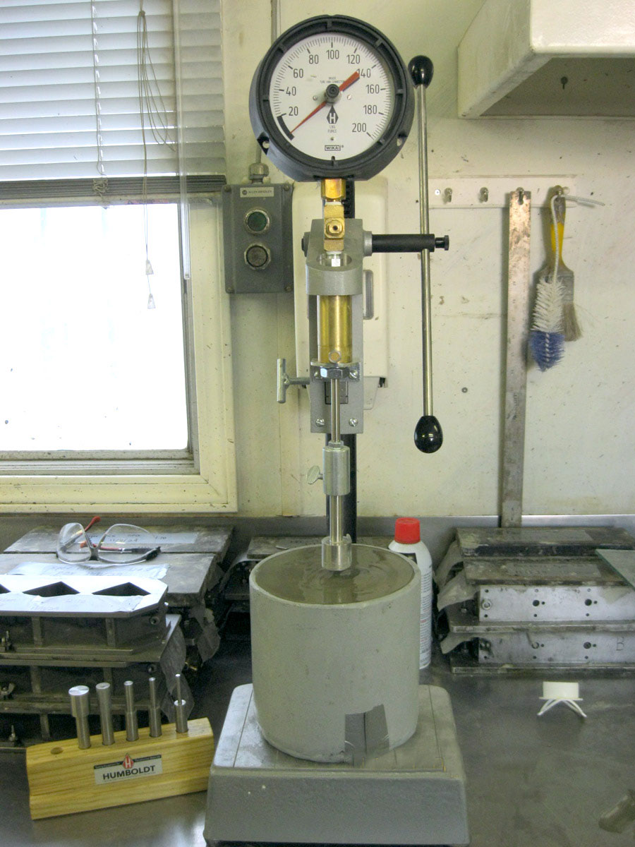
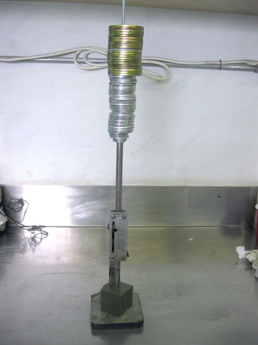
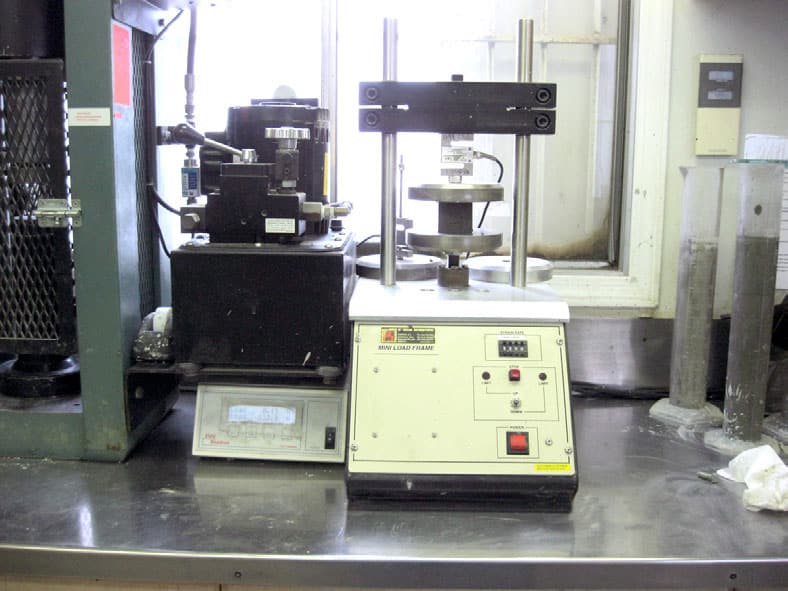
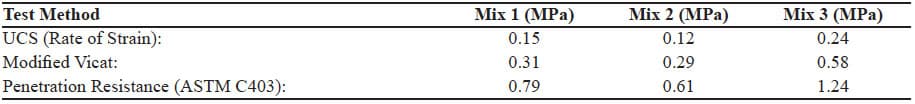
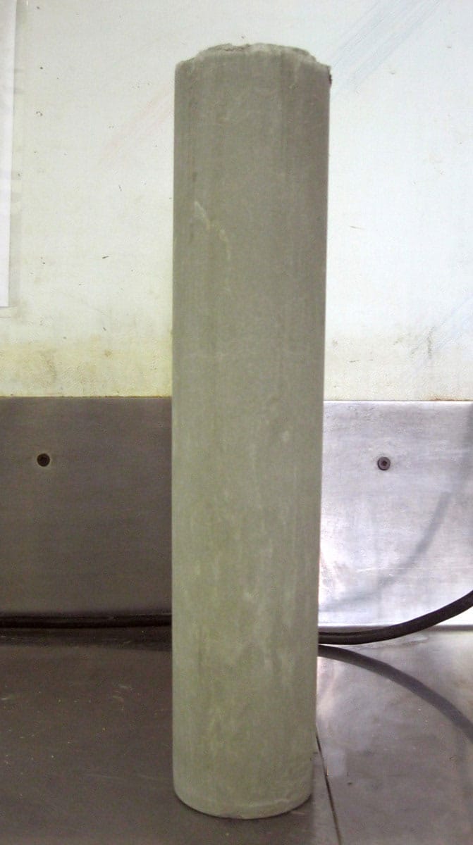
Contractors and suppliers have adapted or developed their own standards to verify grout strengths. The methods vary from penetration resistance (Figure 2), modified Vicat (Figure 3), shear strengths tests, and unconfined compressive tests (Figure 4). When different testing methods are used, different results will be obtained as shown in Table 2. Though penetrometer and Vicat tests do indicate early compressive strengths, they are, at best, an indirect measurement. It has long been standard in concrete and grout testing to test cylinders and cubes as unconfined specimens. Though this is con- servative as the in situ grout will be constrained triaxially, the unconfined compressive strength (UCS) test does provide direct results of the compressive strength. Also, for consistency and correlation of data throughout the test period, it is preferred that the early and later compressive strengths are tested in as similarly as possible. The UCS test, then, provides the most representative data for compressive strengths and the ASTM standards can be referenced from this perspective.
Cubes vs. Cylinders
The standards specify testing for UCS using cylinders having a 2:1 aspect ratio or 2-in (50mm) cubes. It is impractical, however, to use cylinders for early age (<4 hour) and low strength testing as it is difficult to extract the relatively fragile specimens from cylindrical moulds without damaging them. Also, cylinders often require capping to conform to perpendicularity requirements of ASTM C617-10. If cap- ping is necessary, the sample needs to be demoulded at least 10 minutes prior to testing to allow for the capping procedure. If the sample is already fragile at 1 hour, it is only more likely to be damaged if extracted earlier. As the strength gain during the initial hours is significant and notable within 5 minutes intervals as discussed later, the initial cure time is important. Furthermore, 2-in. cubes are commonly used to test grout compressive strengths in reference to ASTM C942 and C109 and, again, samples should be tested as consistently as possible between the specimen ages. For these reasons, ASTM standards to test early compressive strengths using cylinders are not ideal.
Contrastingly, the 2-in. cube moulds can be opened and the specimens removed with little interference to its contents. The mould is stripped from the specimen rather than the specimen from the mould and this can be done relatively quickly. 2-in. cubes can also be poured and screed with more accuracy than cylinders and do not require capping so testing can commence as soon as they are demoulded. Furthermore, they also provide dimensional consistency within the specimen test ages. The 2-in. mould is preferred for these reasons.
It has also been noted that, though ASTM D4832 is designed for controlled low strength material (CLSM) testing in cylinders, it is designed for specimens cured at and beyond 7 days. The difference between curing and cured—plastic and elastic—is important.
Plastic vs. Elastic
During initial hydration and strength gain, the two- component grout is still in a plastic, rather than elastic, state. In other words, loads imposed on an unconsolidated grout sample will cause permanent deformation. During compressive testing, the sample continues to balance loads imposed with axial consolidation, or strain. As the sample consolidates vertically, it expands laterally which increases its cross-sectional area. This area increase needs to be accounted for when calculating the stress.
Plastic testing is common in soils and ASTM D2166-06 outlines the procedure for unconsolidated testing using a rate of strain compressive testing machine. To be clear, cementitious samples are normally tested using a rate of load machine; the amount of load per unit time is monitored. For cured samples this is adequate as elastic failure occurs at or near peak loading. For plastic samples, the rate of strain machine measures the load per unit distance of vertical displacement. This allows for compensation of cross sectional area and these machines are designed and calibrated to test low strength materials.
Although early age grout is in transition from plastic to elastic, there is no clear point of transition. As a general guideline, however, samples may be tested using rate of strain when age <24 hr and/or the strength is <1.5MPa.
A-Component Stabilized Time
The age of the A-Component when the B-Component is added will have an effect on the early strengths of the sample. If, for example, the A-Component is designed to be stabilized for 8 hours and the B-Component is added to one sample at 30 minutes and a second sample at 7 hours since mixing, the 7 hour sample will see higher early strengths as the affect of the retarder would be waning. It should, then, be noted at what time the accelerator is added for testing.
Testing Time
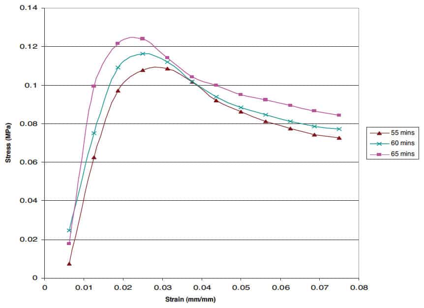
At the early age strengths, the UCS between two specimens tested as little as 5 mins apart can be substantial as shown in Figure 5. Because of this, the rate of strain needs to be optimized to reduce the time for the test while still obtaining adequate resolution. For the 1 hour test, it has been found that starting testing on the first cube at 55 mins, the second at 60 mins and the third at 65 mins gives the best aver- age results for the 1 hour age. The compressive test itself should take 3 to 4 minutes and removing the sample from the testing machine, cleaning the debris and setting the next sample can take 1 to 2 minutes. As a general guideline, strain rates of 1mm/min for strengths of 0.075 to 0.15MPa and 0.75mm/min for strengths of 0.15 to 0.35MPa can be used.
TESTING PROCEDURES
The following is an outline of the testing procedure discussed above. As mixing procedures will vary depending on the equipment and materials, the proposal excludes mixing and sampling procedures and only provides details for testing the finished A-Component and accelerated grouts.
Flowability
ASTM C939 is used to test flowability of the A-Component with the following amendment and additions:
- Mixing equipment and methods similar or the same as the final equipment should be used in place of C939.7.6.
- The flowability should be checked at repeated intervals depending on the characteristics of the project. At a minimum, flow is taken immediately after mixing, at a mid-point and then at the end of required pot life of the grout.
- If a viscometer is available, viscosities should be recorded at the same time the flows are.
- Field testing indicated that flow times less than 17 secs and viscosities less than 125 cps are preferred. This can vary depending on tunnel requirements and pumping equipment used.
Bleed
ASTM C940 is used to measure bleed and if internal segregation is noted. Depending on the pot life required, the bleed is noted at intervals throughout this time, along with flow, and may extend past the three hour standard often referenced for this test. The bleed water should be decanted off as indicated in C940.9.5 of the standard and then the sample allowed to set in the cylinder. Once set, the cylinder can be turned over and the top hit on a firm surface to free sample—usually not as difficult to do as might be expected (Figure 6). Bleed should be less than 3% at 8 hours.
Gel Time
A simple procedure has been observed and tested to help quantify the gel time which is to pour the mixed grout back and forth between two containers until it will not pour any longer (Pellegrini, Perruzza 2009). The following is a variation of this procedure:
- Weigh 1 kg samples of A-Component in container suitable to mix the B-Component into.
- In a graduated cylinder, measure proportioned amount of accelerator for the 1 kg sample of A-Component.
- Have a second clean and empty container of equal size ready.
- While vigorously mixing with the A-Component, quickly add the B-Component in while starting the time and continue to mix for 5 seconds.
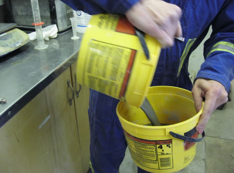
- Continue to mix the components by pouring from one container to the other until it will not flow any longer (Figure 7 and Figure 8).
- Record the time from when the accelerator was first added to when the grout would not flow as the gel time.
A and B Component Mixing
Depending on the characteristics of the specific retarder and accelerator, this procedure may need some modification. However, for mixes similar to the tests used for this paper, the follow procedure provides consistent samples:
- Weigh 1 kg samples of A-Component in a container suitable to mix the B-Component into.
- In a graduated cylinder, measure proportioned amount of accelerator for the 1 kg sample of A-Component.
- Prepare a three-gang specimen mould per ASTM C109 5.3 and 9.1.
- While briskly hand mixing the sample of A-Component, quickly pour the B-component in and continue to mix for 5 seconds. The mix will be more fluid for approximately 5–15 seconds (Figure 9).
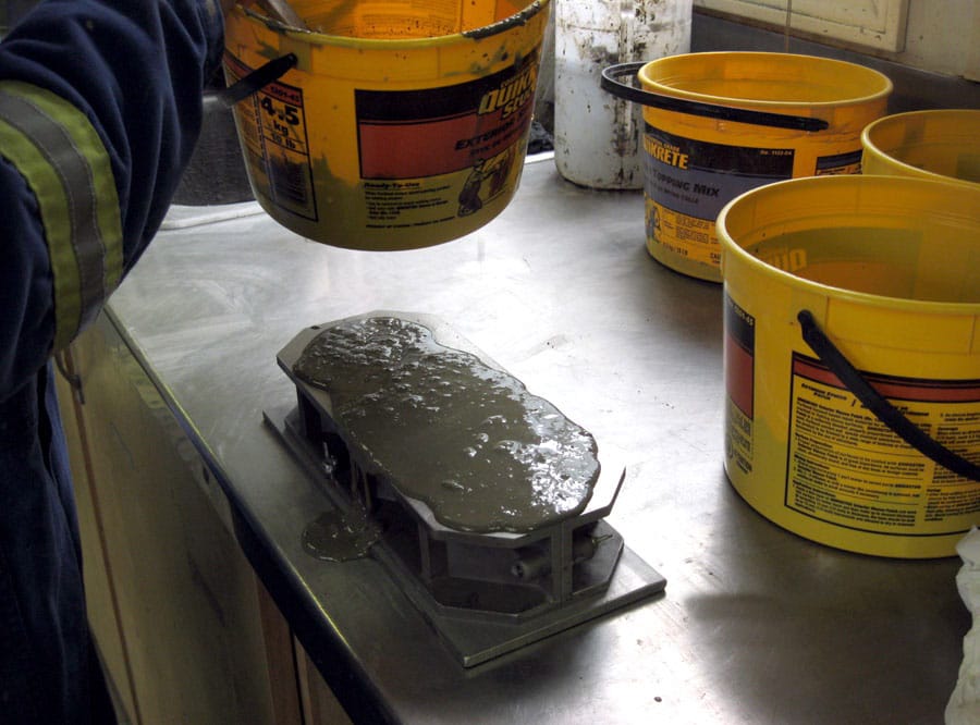
- Quickly pour the accelerated grout into each of the three cube moulds in a single pour; there will not be enough time to fill half way and tap surface per C942 10.3.2 (Figure 10 and Figure 11).
- The mix will generally set within 30 seconds and the excess grout must be cut off (ASTM C942 10.3.2).
- The mould can then be covered and stored per C942.
Compressive Strength
The compressive strength should be measured by two separate methods, depending on the age and curing properties.
Early Age
At < 24 hrs or 1.5MPa, the sample should be tested using rate of strain and referencing ASTM D2166 with the follow exclusions or amendments:
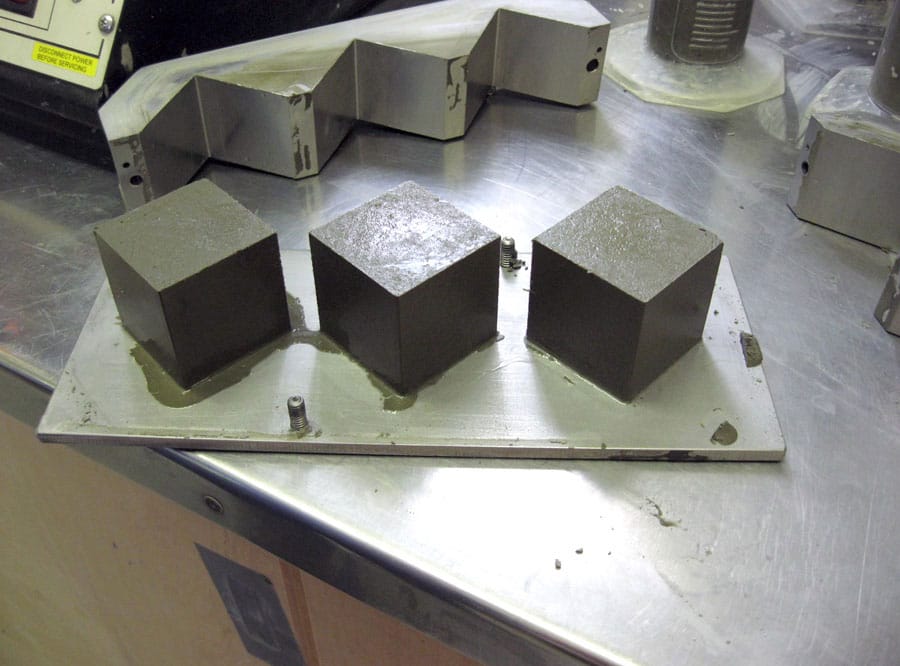
- D2166.5.2 is excluded as the cube samples can be easily demoulded (Figure 12).
- D2166.6 is excluded as the sample size will be 2-in. (50mm) cubes and the specimens created as described in “A and B Component Mixing” above.
- The procedure in D2166.7 needs to include an emphasis on time with early age samples. The rate of strain in 7.1 of ½ to 2% needs to also consider that the test must be completed within 4 minutes as discussed previously.
- D2166.9 should be modified to suit the annulus mix design and dry densities, saturation, etc., do not apply.
- D2166.10 was substituted with C109.13 and .14.
Later Age
For UCS testing > 24 hours or 1.5MPa C109.10.7–14 are used.
CONCLUSION
It has been shown that different procedures used to commonly test the early compressive strengths of two-component grouts can have a substantial impact on the results. This paper has described that for strengths less than 1.5 MPa and times less than 24 hours, a rate of strain unconfined compressive testing method should be used to accurately predict the compressive strengths of two-component grouts. Furthermore, procedures quantifying the flowability, bleed and gel time have been proposed based on applicable and, where necessary, modified ASTM standards. The intention is to provide the tunnelling industry a base for two-component grout testing procedures.
REFERENCES
ASTM C109-08 Standard Test Method for Compressive Strength of Hydraulic Cement Mortars (Using 2-in. or [50-mm] Cube Specimens).
ASTM C617-09 Standard Practice for Capping Cylindrical Concrete Specimens.
ASTM C938-10 Standard Practice for Proportioning Grout Mixtures for Preplaced-Aggregate Concrete.
ASTM C939-10 Standard Test Method for Flow of Grout for Preplaced-Aggregate Concrete (Flow Cone Method).
ASTM C940-10a Standard Test Method for Expansion and Bleeding of Freshly Mixed Grouts for Preplaced-Aggregate Concrete in the Laboratory.
ASTM C942-10 Test Method for Compressive Strength of Grouts for Preplaced-Aggregate Concrete in the Laboratory.
ASTM D2166-06 Standard Test Method for Unconfined Compressive Strength of Cohesive Soil.
ASTM D4832-02 Standard Test Method for Preparation and Testing of Controlled Low Strength Material (CLSM) Test Cylinders.
Feddema, A; Moller, M.; van der Zon, W.H.; Hashimoto, T. ETAC Two-Component Grout Field Test at Botlek Rail Tunnel.
Noppenberger, C and Reschke, A, 2 Brisbane Airport Link Earth Pressure Balance Machine Two Component Tailskin Grouting—A New Australian Record 2011.
Peila, Daniele; Borio, Luca; Pelizza, Sebastiano. The Behaviour of a Two-Component Back-Filling Grout used in a Tunnel-Boring Machine. ACTA Geotechnica Slovenica. 2011.
Peila, Daneile; Borio, Luca; Pelizza, Sebastiano. The Behaviour of a Two-Component Back-Filling Grout Used in a Tunnel-Boring Machine. ACTA Feotechnica Slovenica January 2011.
Pellegrini, Lorenzo; Perruzza, Pietro. Sao Paulo Metro Project–Control of Settlements In Variable Soil Conditions Through EFB Pressure and Bicomponent Backfill Grout. RETC June 2009.