Reschke, A.E.
Originally published – The Development of Colloidal Mixer Based CRF Systems. In MINEFILL 98, Edited by Dr. M. Bloss. Carlton, Australia: Australian Institute of Mining and Metallurgy. pp. 65-70.
ABSTRACT
The high-shear colloidal mixer is generally recognised as the most efficient method of mixing cement based grouts. Only recently however has this technology been applied to the production of cemented rockfill (CRF) for use in underground mines in North America.
Traditionally, paddle type mixers have been used to produce the cement based slurries required for the preparation of CRF. While considerable success has been achieved with these mixers, tremendous advantages are attained with the colloidal mixer. The combined effect of the highly efficient mixing action and the ability to mix low water/solids ratios, allows for reductions in the cement content for a given strength requirement. Cement can also be replaced by cheaper fillers such as flyash, resulting in further cost savings.
Although large-scale dedicated CRF batching plants are typical, there is a growing need for mobile plants capable of operating anywhere underground. The compact size and rapid batching speed of high-shear colloidal mixers has allowed them to be incorporated into skid mounted systems capable of producing and discharging cement based slurries onto rockfill aggregate for the production of CRF. In many cases run-of-mine development waste can be used as CRF aggregate with these slurry plants thereby reducing the cost of waste rock removal. These relatively low cost portable plants have now allowed several mines to economically recover isolated pillars and realise positive returns on their investment.
INTRODUCTION
The logistics of underground mining often require the mined out voids to be backfilled, for reasons ranging from providing a working surface for equipment to controlling local and regional ground stability. While there are many types and variations of backfill to choose from, economics, mine geometries, geotechnical and environmental concerns will dictate the final selection of fill type, which is quite commonly a cemented rockfill, or CRF.
Cemented rockfill in its simplest form is comprised of three basic ingredients, a graded rock aggregate, a cementitous binder and water. These components are mixed together and are either conveyed or trucked to the placement area.
Typically one of two possible methods for preparing CRF is employed. The first method uses concrete batching technology whereby all the mix ingredients are added together into a rotary drum, pan, or ribbon type batching mixer. The second and more common method is to prepare the cement based binder in a slurry form, usually with a paddle mixer, and subsequently spray this binder over the backfill aggregate. While paddle type mixers do yield adequate results, as evidenced by the number of mines using this technology, a more efficient type of slurry mixer is available – the colloidal mixer.
Keller Colcrete successfully pioneered the development of the high-shear colloidal mixer in 1937 and for over 60 years it has been internationally recognised as the most efficient method of mixing cement based grouts (Houlsby, 1990). These mixers are used in grout preparation for radioactive waste encapsulation, hydro dam grout curtains, soilcrete jet grouting, soil nailing, and numerous other geotechnical applications. In tunnelling, these mixers are used for ground treatment, compensation grouting and for the preparation of bentonite lubrication for pipejacking and tunnel boring machine (TBM) operations.
It has been only within the last few years however that these high-shear colloidal mixers have been adapted for use in the preparation of cemented rockfill within the North American mining industry.
PRINCIPLES OF HIGH-SHEAR COLLOIDAL MIXING
Colloidal mixer design
While several brands of colloidal mixers are now available, the Colcrete mixer design will be discussed below. Readers are referred to Houlsby (1990) for a more detailed design comparison of other commercially available colloidal and paddle type mixers.
Colloidal mill
The key element of the colloidal mixer is the colloidal mill (see Figure 1). The mill is comprised of a high speed rotor (or discar) operating at 2000 rpm coupled with a close fitting chamber housing. The discar is free to float horizontally on its mounting shaft with the internal fluid pressures centralising it in the housing. The clearance between the discar and the walls of the housing is approximately 3 mm. It is here that a violent turbulence and high shearing action is created which is capable of breaking down clusters of dry cement particles (agglomerates).
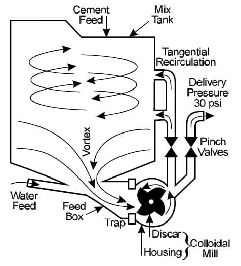
The colloidal mill also acts as a centrifugal pump. In a CRF plant the colloidal mixer can thus directly discharge a mixed slurry either into a holding hopper or directly onto the rockfill aggregate in a haul truck or LHD. The colloidal mill is capable of generating a maximum discharge pressure of 200 kPa and a flowrate of up to 850 l/min. It is possible to increase the mills efficiency as a pump (thus giving it a higher pressure capacity) but this would reduce its efficiency as a mixer. This lower pump efficiency translates into more work being done on the material being mixed, ie more energy input.
Depending on the required batch size of the mixer, one to four colloidal mills will be used per tank. Each mill requires either a 22 kW electric motor or appropriately rated diesel or air motor equivalent.
Mixing tank
The mixing tank, besides holding all the ingredients, also acts as a centrifugal separator. The centrifugal action of the circulating material spins the unmixed, thicker grout towards the outside of the tank whereas the lighter portions of the mix, ie the water and partly mixed grout, move inwards towards the throat of the tank and into the colloidal mill. Once through the mixer this lighter material is discharged tangentially into the outer part of the vortex, thus blending with the thicker, unmixed grout. Multiple passes through the rotor produce thicker and thicker grout until the entire mix becomes uniform and the centrifugal action can no longer separate differing densities. At this point the surface of the vortex has a smooth, uniform appearance.
The vortex action created inside the tank also helps to rapidly assimilate any admixtures into the mixer when first added. Depending on the size of the mixer the entire mixing process can take as little as 15 seconds.
Feed box
The feed box to the rotor housing is of ample proportion to ensure large lumps of unmixed cement at the start of the mixing cycle are able to pass through to the rotor. These lumps can be quite sticky on the first pass before being broken up.
Control valves
The output from the colloidal mill is split into two paths. Either the slurry is redirected tangentially back into the drum, to help create the vortex action, or it is discharged. Simple pneumatic or manual pinch valves are used to control this flow.
Colloidal suspensions
While the term ‘colloidal’ is often applied to high-shear mixers and the slurries they produce, strictly speaking, the term is incorrectly applied. ‘Semi-colloidal’ or ‘near-colloidal’ are more accurate descriptions. A colloid is defined as a solid, liquid, or gaseous substance made up of very small, insoluble, nondiffusible particles (as large molecules or masses of smaller molecules) that remain in suspension indefinitely in a surrounding solid, liquid, or gaseous medium of different matter. With cement based slurries, it is possible to filter out the solids (though perhaps not all if the cement is microfine) and individual grains can readily be seen. Particles will settle out leading to grout bleed. Cement slurries are thus not true colloidal suspensions.
The effect of the colloidal mixer, however, is to aggressively shear and break down individual cement grains and to make cement hydrates form of colloidal size such that the slurry exhibits colloidal properties, ie the slurry forms a stable suspension.
Properties of high quality grouts and slurries
A high quality grout or slurry is regarded as having the following properties (Houlsby, 1990).
- Every particle of cement in the mix is thoroughly wetted. Individual grains are separate from each other without flocs or clumps.
- Each cement grain is surrounded by a film of water which chemically activates the particle, giving the full hydration necessary for strength and durability.
- The cement is thoroughly mixed with any other constituents of the mix or admixtures.
- The grout or slurry is uniform throughout.
- The mix exhibits some colloidal characteristics because of the maximum gel formation of the cement.
All of these properties can be attained with the use of high- shear, high-speed colloidal mixers. Kravetz (1959) explains that the high-speed shearing action combined with the centrifugal action of colloidal mixers thoroughly breaks up cement clumps and separates air bubbles, both of which slow the wetting process of cement grains. As a result, each grain is rapidly and thoroughly wetted and put into suspension. The mixing action also continually breaks away the hydrates that form on the surface of wetted cement grains exposing new areas to water. The hydrate elements that form are of colloidal size and as the amount of these elements increases the mixture becomes more colloidal in character.
Mayer (1959) measured the effect of high-shear colloidal mixing on cement grain size, particularly grains under 20 µm in size. The percentage of grains 5 µm in size was shown to be twice as large after high-speed mixing than with ordinary mixers, which accounted for the fact that the suspensions obtained were much more stable.
Practical benefits of colloidally mixed products
The practical benefits of colloidally mixed grouts and/or slurries include:
- The grout or slurry mix is nearly immiscible in water. This allows the mix to resist washout or contamination with groundwater.
- The mix is stable and fluid enough to allow it to be pumped considerable distances.
- The slurry permeates uniformly into voids.
- Segregation of sand, if incorporated in the mix, is virtually eliminated.
- The grout or slurry has less settlement, ie bleed of the cement when stationary.
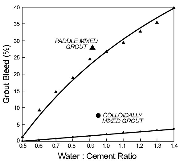
To illustrate the benefits of colloidally mixed grouts, comparative tests were conducted using grout prepared from type ten ordinary Portland cement (OPC) and water. A Colcrete SD4 colloidal mixer and a Thiessen Team TC3100 paddle mixer were used to prepare slurry samples ranging from a 0.5 to 1.4:1 water:cement ratio. The samples were mixed for one minute in the colloidal mixer, 15 minutes in the paddle mixer. Cylinders 7.6 cm in diameter and 15.2 cm high were used for sample preparation.
Figure 2 depicts the results of grout bleed as measured from the cured samples. The colloidally mixed slurries formed stable suspensions and consequently very little settling of cement grains occurred. Grout bleed was minimal, less than four per cent in the thinnest grout. The paddle mixed samples however had grout bleeds approaching 40 per cent in the 1.4:1 water:cement ratio mix. The cement particles simply settled out before significant hydration could occur. Clearly the low-energy paddle mixer was not able to adequately break down individual cement grains.
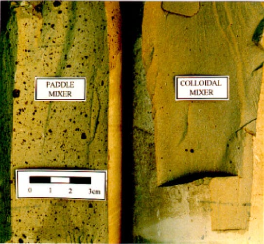
Figure 3 shows a section through the 0.5:1 water:cement ratio samples. The colloidally mixed product exhibits a uniform colour and texture and appears virtually homogeneous whereas the paddle mixed sample has a grainy texture with individual cement clumps visible. Colour variations were also evident in all the paddle mixed samples.
Unconfined compressive strengths were determined utilising ASTM D-2938-86 procedures and plotted in Figure 4. It is evident that the data points for the colloidally mixed samples exhibit less scatter than the data points for the paddle mixer prepared samples. This implies that the colloidal mixer is capable of producing a more consistent, more uniform product. Secondly, the strength of the colloidally mixed samples shows an average 10 MPa strength improvement for a given density. The ability of the colloidal mixer to break down and wet all the cement agglomerates yields an improved 28-day compressive strength.
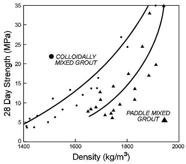
The improved performance of the colloidally mixed product has tremendous cost saving implications. For example, to produce a 25 MPa grout strength, a colloidally mixed product requires a cured density of some 1650 kg/m3 whereas, a paddle mixer prepared product requires a higher density approaching 1810 kg/m3 (from Figure 4). Based on theoretical densities this translates to a 13 percent reduction in cement content for the product prepared in a high-shear colloidal mixer. Clearly there is the potential to save significantly on the most costly component of CRF – the cement.
Admixtures and colloidal mixers
The ability of colloidal mixers to accept admixtures and sands are also important benefits. Sands, ie fines can be incorporated directly into the mixer up to a maximum sand:water ratio of 4:1 by weight so long as a minimum water:cement ratio of 1.12:1 is maintained. Sand should be well graded with a maximum particle size of 5 mm. Conversely, if no sand is added, water:cement ratios as low as 0.33:1 can be handled by the mixer. This also makes the colloidal mixer well suited for the preparation of grout used in cablebolting where the optimal water:cement ratio should be in the range of 0.35 to 0.4:1 (Hutchison and Diederichs, 1996).
Flyash, silica fume and other additives can all be incorporated into the mixer along with the cement. For maximum advantage these materials should have a particle size less than or equal to the cement particle size. Flyash should show no more than eight per cent loss on ignition. Admixtures, lime and even bentonite can all be mixed with the colloidal mixer.
Factors contributing to CRF performance
Besides the quality of the cement slurry, a number of other factors also contribute to the final in situ strength of placed CRF. These factors include (Yu and Counter, 1983; Yu, 1989; Reschke, 1993; Farsangi, Hayward and Hassani, 1996):
- cement content
- water:cement ratio of the slurry,
- nature and quality of admixtures such as flyash and PFA,
- degree of mixing between the cement slurry and fill aggregate,
- composition and quality of aggregate,
- aggregate size distribution and percentage of fines,
- segregation of material during placement,
- attrition of aggregate during transport and placement, and
- aggregate temperature (ie freezing conditions).
There are a great number of factors contributing to the strength of a cemented rockfill. However, because of the obvious importance of the cement itself, the colloidal mixer with all its advantages offers a great opportunity for long-term cement (and cost) savings in any CRF operation.
CURRENT COLLOIDAL MIXER BASED CRF PLANTS
The use of high-shear colloidal mixers for CRF slurry plants within the North American mining industry was pioneered by Thiessen Team, who have designed and built six plants for underground hard-rock mines within the past three years. Several of these mines and their respective systems are highlighted.
Lamefoot Mine, Republic, Washington (USA)
Lamefoot is a recently opened 1350 tpd longhole open stoping operation owned and operated by Echo Bay Minerals. A cemented rockfill was selected early on in the mine design process to maximise extraction without losing reserves in irrecoverable high grade pillars.
This mine was the first operation in North America to utilise a colloidal mixer within a CRF slurry batching plant. Constructed in 1995, the plant is located underground, adjacent to the main portal. The primary cement storage silo is situated outside of the mine and uses a blower to charge a small 22 tonne surge silo at the slurry plant. Both the cement and water are weigh batched in separate hoppers that feed into a Colcrete SD1000 (1000 litre) colloidal mixer.
The entire system is PLC (programmable logic controller) based for unattended operation. A 0.8:1 water:cement ratio batch of slurry is prepared using 680 kg cement and 545 kg water. This is initiated remotely with a pull-bob system by the haul truck operator upon approach to the plant. Batching time takes less than two minutes.
The haul trucks have a capacity of 14.5 tonnes but typically hold 11.8 tonnes of rockfill aggregate. The prepared grout slurry is dispatched through a spraybar directly onto the aggregate in the truck box. The discharge is initiated by a second pull-bob located at the spraybar assembly. Discharge takes less than one minute after which the PLC initiates a cleaning cycle, flushing a small quantity of water through the mixer and discharge lines.
Run-of-mine development waste, with a maximum size of 45 cm, is used as aggregate. While daily fill production has reached as high as 1100 tpd, the average daily fill rate is considerably lower. A monthly fill rate of 10 000 tonnes is typical which is well below the plants capacity.
Because the cemented rockfill is end dumped over the stope face, some segregation occurs as the aggregate falls. This has been seen in subsequent exposures. Nonetheless, excellent performance has been achieved as evidenced in fill exposures 25 m high by 40 m along strike which remain intact with virtually no dilution. Part of the success is attributed to the quality of the slurry prepared by the colloidal mixer.
Backfill strength is monitored regularly through underground sampling. Cylinders 15 cm diameter are prepared from the dumped rockfill (excluding aggregate greater than 7.5 cm). Compressive strengths of 4.8 MPa are typical (Thompson, 1997).
Myra Falls Mine, Campbell River, B C (Canada)
Westmin Resources Myra Falls Mine, in production since 1966, historically utilised room and post-pillar mining methods along with traditional cut-and-fill. Since 1991 however, bulk mining methods have been incorporated to reduce costs and increase production to the current level of 3650 tpd. While cemented hydraulic fill is used extensively, the mine is currently in the process of developing a high-density fill system.
A newly delineated ore zone, located some distance away from the existing underground infrastructure, was recently developed. Longhole open stoping methods were selected with consolidated fill to be placed in primary stopes. Scheduling requirements dictated the need to be producing ore from secondary stopes relatively early on in the mine plan. However, no backfill was yet available in this new zone. To meet the short-term requirements a small-scale portable CRF slurry system was brought in.
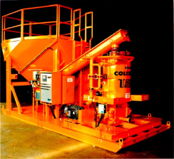
This slurry batching plant (similar to Figure 5) was designed around a Colcrete SD24 (680 liter) colloidal mixer and skid mounted to be fully portable underground. As the mine is accessible by shaft only the major components simply unbolt into cageable sizes. Fully constructed the plant is under 4.2 m high.
A 6.5 tonne holding hopper contains the cement for the plant. This hopper is in turn filled by 0.9 tonne bulk bags of cement through a bag unloading bin and feed conveyor. A PLC monitors the cement content of the holding hopper by way of a radio frequency probe and also aerates the hopper to promote cement powder flow.
The key to the success of the plant design is the placement of the entire colloidal mixer platform atop load cells. The colloidal mixer hopper thus functions as a mixer and as a scale to accurately weigh the cement and water. This layout optimises the size of the system and increases the batching speed as the cement is constantly being mixed as it is augered into the mixer.
The PLC controls all facets of the plant operation including the batch recipes for either truck size or LHD size quantities of slurry. The slurry is discharged through a spraybar assembly. On completion the mixing tank partially fills with water and the colloidal mill is run to purge itself, the mixing hopper and all delivery lines. The systems self-cleans and operates with minimal human intervention. By skipping the purge cycle the system is capable of discharging a full batch of slurry every two minutes.
A five per cent CRF utilising run-of-mine development waste was produced and used in the extraction of one pillar block. Soon after the successful recovery of this pillar the plant was retired. The infrastructure was finally developed for the mines conventional cemented hydraulic fill and despite the positive financial return on the CRF venture (Powers, 1997), hydraulic fill was deemed to be more cost effective in the long-term.
Based on the success of this portable plant concept, Cominco Ltd has just commissioned a slightly larger version of this system (shown in Figure 5) for their Sullivan mine. Once again, a CRF system was deemed economically viable for selective pillar recovery. This plant is more elaborate however than Westmin’s, incorporating both a dust collection system and a PLC controlled bulk cement bag unloader. Work is currently underway on the recovery of the first pillar.
Polaris Mine, North West Territories (Canada)
Cominco’s Polaris Mine, located in the Canadian high arctic, has the distinction of being the world’s most northerly base metal mine. The mining method incorporates sublevel longhole open stoping with backfill. Primary stopes are 15 m in width and range from 100 to 150 m in length and from 60 to 110 m in height. Secondary stopes (pillars) are of similar dimensions but are 18 m in width. Stopes are mined full length in 30 m lifts (pillars in 25 m lifts). Raisebore holes 1.8 m in diameter are drilled from the stopes to surface and are used for ventilation, slotting and backfilling.
The primary fill system utilises a 50/50 mix of quarried surface rock and underground waste rock. The fill is mixed with 11 per cent water by weight and pushed into the stopes where, after 1.5 to 2 years, a frozen 3.0 MPa fill is attained. During the summer months, a wetter, more flowable backfill mixture is dumped from the surface into the tops of previously filled stopes to ensure a tight fill to the hangingwall. This backfill takes considerably longer to freeze because of the latent heat of fusion associated with the higher moisture content.
In 1995 the possible use of CRF to supplement the frozen rockfill system was investigated. Future pillar extraction plans called for a backfill that would offer superior stiffness properties (for improved ground control) and be capable of developing high early strengths (for increased cycle times) as compared to the existing frozen fill. Polaris also faced the added challenge of making a reliable cemented product in permafrost conditions where surface temperatures range from -55ºC in the winter to +10ºC in the summer.
Owing to the severe attrition associated with 250 m dump heights, the surface quarried CRF aggregate is screened to a size range of 12.5 to 200 mm. After dumping, tests have shown this yields a placed aggregate with approximately 45 per cent passing 10 mm (Dismuke and Diment, 1996).
With vertical exposures required of up to 100 m, a minimum CRF compressive strength of 2.5 MPa was deemed necessary. In order to achieve this strength in situ, a controlled lab strength of 5.0 MPa was targeted. Ultimately, a CRF product capable of developing 4.9 MPa in the lab was developed using five per cent type 30 high early strength cement prepared at a 0.7:1 water:cement ratio. Five per cent calcium chloride (by weight of cement) is also added to the slurry.
The use of calcium chloride as an accelerator is limited, in most civil engineering applications, to two per cent by weight of cement. Higher dosages give decreased concrete strengths at later stages because of the break down of calcium chloride over time. However, at the colder temperatures found at the mine site, the break down occurs considerably slower and is negligible in terms of the required life span of the fill.
Winter temperatures also result in the rockfill aggregate being as cold as -30ºC. To meet the fill requirement of 3000 tpd, a 3.0 MW hot water aggregate heating circuit was designed, capable of warming the aggregate at a rate of 125 tph to a final temperature of +15ºC. To produce the required slurry, a 2000 litre capacity colloidal mixer was developed by Thiessen Team in conjunction with Keller Colcrete. The largest ever produced, this mixer incorporates four colloidal mills to provide rapid, efficient mixing of the water, cement and calcium chloride.
As the entire CRF plant is located on surface, the complete circuit is enclosed and fully heated. Heated aggregate is stored in a surge bin and conveyed to a heated load out structure. The original design called for the aggregate to be dumped through a ‘ladder’ mixing chute (a chute with angled baffle plates on the walls) with the slurry being sprayed on the aggregate as it enters the chute. It was believed this ‘mixer’ would improve the mixing of the slurry and the aggregate. In practice however, freezing problems were encountered in the chute and now the slurry is dumped directly onto the aggregate in the truck box.
The CRF haul trucks have a fully enclosed dump box with a hydraulically operated hatch on top through which the CRF is loaded. This box is heated with engine exhaust. From the load out, the truck proceeds to the raisebore hole and dumps the CRF into the stope.
The system became fully operational in March 1996 and has been successfully used to eliminate post-pillars in one zone of the mine. Seven pillar stages have been filled to-date with some 265 000 tonnes of fill. Five full face exposures of the CRF have been made, the largest being 90 m high by 18 m wide. Results have been very favorable with fill dilution well below five per cent.
Part of the success has been attributed to the placement of the raisebore holes. Since the CRF is dumped from surface the compacted zone of fill (directly under the raisebore hole) typically has the highest strength. This is positioned immediately adjacent to the next mining face. In larger pillar stages, two raisebore holes are used to place both CRF and dry fill in the same void at opposite ends. This significantly reduces the amount of CRF required.
Owing to the success to-date, future plans call for a ten per cent reduction in the cement content of the CRF to 4.5 per cent in an attempt to reduce costs. This reduction is based strictly on favorable in situ observations of the placed CRF.
Meikle Mine, Carlin, Nevada (USA)
The Meikle Mine, owned and operated by Barrick Gold, was brought into full production late in 1996 at a scheduled mining rate of 1900 tonnes/day. Although the orebody is relatively shallow, only 300 to 600 m below surface, the ambient rock temperature averages 60ºC thus necessitating the installation of a 10 MW refrigerative plant (White and Kral, 1994). While some cut-and-fill mining may be required where geometry dictates, the predominant mining method is sublevel longhole open stoping with consolidated backfill. Cemented rockfill was selected as the optimal method of backfilling.
The primary backfill plant on-site consists of a 7.6 m3 Besser ribbon mixer. Aggregate is produced from pit waste that is shipped directly to a crushing and sizing plant. A single product is produced consisting of less than 5 cm size particles with 40 per cent passing 9.5 mm. The aggregate is transferred dry to the underground backfill plant through three 305 mm ID vertical transfer pipes located in the ventilation shaft. A CRF strength of 4.1 MPa is targeted for primary stoping where the fill will not be undercut. A 6.9 MPa strength is required for underhand cut-and- fill mining areas.
A small-scale CRF slurry system was acquired as a back-up to the primary system to ensure production requirements would be met. A Colcrete SD1000 colloidal mixer based system was selected. The mixer is located adjacent to the main CRF plant diverting the cement feed from the Besser mixer into a small aerated surge bin. The colloidal mixer is mounted on load cells to weigh the water and cement. The cement is mixed as it is augered into the colloidal mixer hopper thus reducing batch times. A pulse jet dust collection system de-dusts the plant and feeds the reclaimed cement back into the feed auger to the mixer.
The CRF slurry system went on-line in January 1997. Typical cement contents are 6.3 per cent by weight of fill. Spraybars are located on two separate levels within the mine. A batch of slurry is initiated remotely with call buttons and varies from 455 kg to 545 kg of water per 725 kg cement depending on the level. The slurry is sprayed onto approximately 11.5 tonne loads of run-of- mine waste rock in 14.5 tonne haul trucks. While typical daily production rates are lower, this back-up system has been called on to produce in excess of 1600 tpd.
Following the discharge of a batch of slurry the plant weighs the water to be used in the next batch and utilises this water to purge the discharge lines, scour the mixer and flush the spraybar. The discharge return lines actually pressure-wash the interior of the mixer through an axial spray nozzle. This allows the plant to operate virtually maintenance free.
CONCLUSIONS
While paddle mixers have traditionally been used to produce the cement based slurries required for cemented rockfills, it is evident that a high-shear colloidal mixer is capable of producing a superior quality product. The combined effect of the highly efficient mixing action and the ability to mix low water/solids ratios allows for reductions in cement content for a given strength requirement and thus cost savings. To-date, six mining operations in North America have, or are currently using colloidal mixers and all have reported excellent performance from the placed cemented rockfill, even when using run-of-mine waste as aggregate.
Colloidal mixers have been incorporated into both surface and underground permanent installations. The compactness and high batching speed of these mixers has also allowed them to be developed into self-contained, portable, skid mounted systems capable of operating anywhere underground to produce high quality slurries for the production of CRF. This recent advancement has allowed several mines to examine the economics of pillar recoveries and realise that positive returns on investment are possible with these relatively low cost portable plants.
REFERENCES
Dismuke, S and Diment, T, 1996. The testing, design, construction and implementation of cemented rockfill (CRF) at Polaris, CIM Bulletin, 89(1005):91-97.
Farsangi, P N, Hayward, A G and Hassani, F P, 1996. Consolidated rockfill optimization at Kidd Creek Mines, CIM Bulletin, 89(1001):129-134.
Houlsby, A C, 1990. Construction and Design of Cement Grouting – A Guide to Grouting in Rock Foundations, pp 10-28 (John Wiley & Sons:New York).
Hutchison, D J and Diederichs, M, 1996. The Cablebolting Cycle – Underground support engineering, CIM Bulletin, 89(1001):117-123.
Kravetz, G A, 1959. Cement and clay grouting of foundations: The use of clay in pressure grouting, ASCE Journal of Soil Mechanics and Foundation Division, 85(SM2):109-114.
Mayer, A, 1959. Cement and clay grouting of foundations: French grouting practice, ASCE Journal of Soil Mechanics and Foundation Division, 85(SM1):41.
Powers, B, 1997. Personal communication, November.
Reschke, A E, 1993. The use of cemented rockfill at Namew Lake mine, Manitoba, Canada, MINEFILL 93, (Ed: H W Glen), pp 101-108 (SAIMM: Johannesburg).
Thompson, D, 1997. Personal communication, November.
White, L and Kral, S, 1994. American Barrick, Mining Engineering, 46(11):1231-1242.
Yu, T R, 1989. Some factors relating to the stability of consolidated rockfill at Kidd Creek, Innovations in Mining Backfill Technology, (Eds: F P Hassani, M J Scoble and T R Yu) pp 279-286 (Balkema: Rotterdam).
Yu, T R and Counter, D B, 1983. Backfill practice and technology at Kidd Creek Mines, CIM Bulletin, 76(856):56-65.