Only a few days until The North American Tunneling Conference in Philadelphia, PA! The Simem Underground team will be at booth# 416 from June 19-22. Please plan on stopping by to say hello!
More info here.

June 15, 2022
Only a few days until The North American Tunneling Conference in Philadelphia, PA! The Simem Underground team will be at booth# 416 from June 19-22. Please plan on stopping by to say hello!
More info here.
June 13, 2022
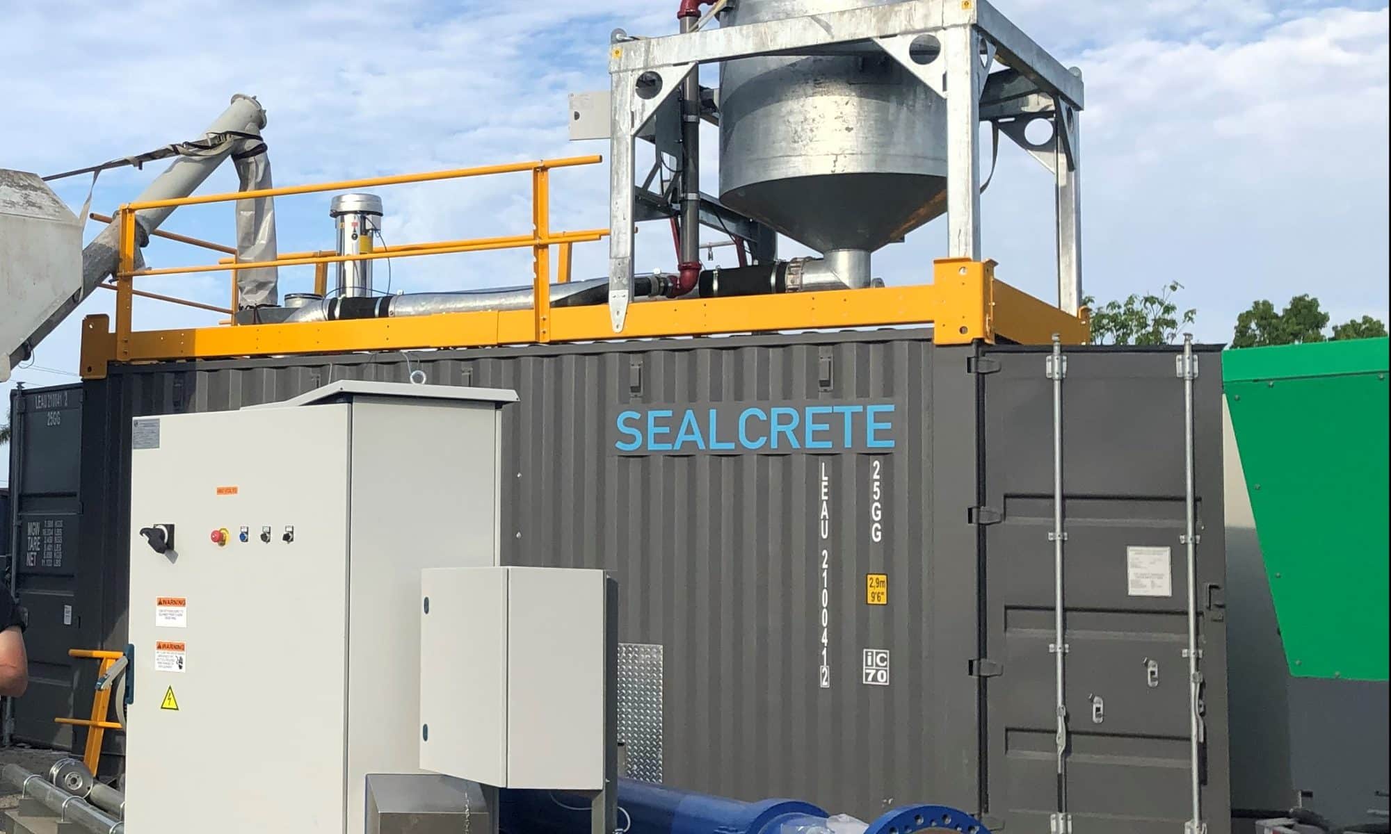
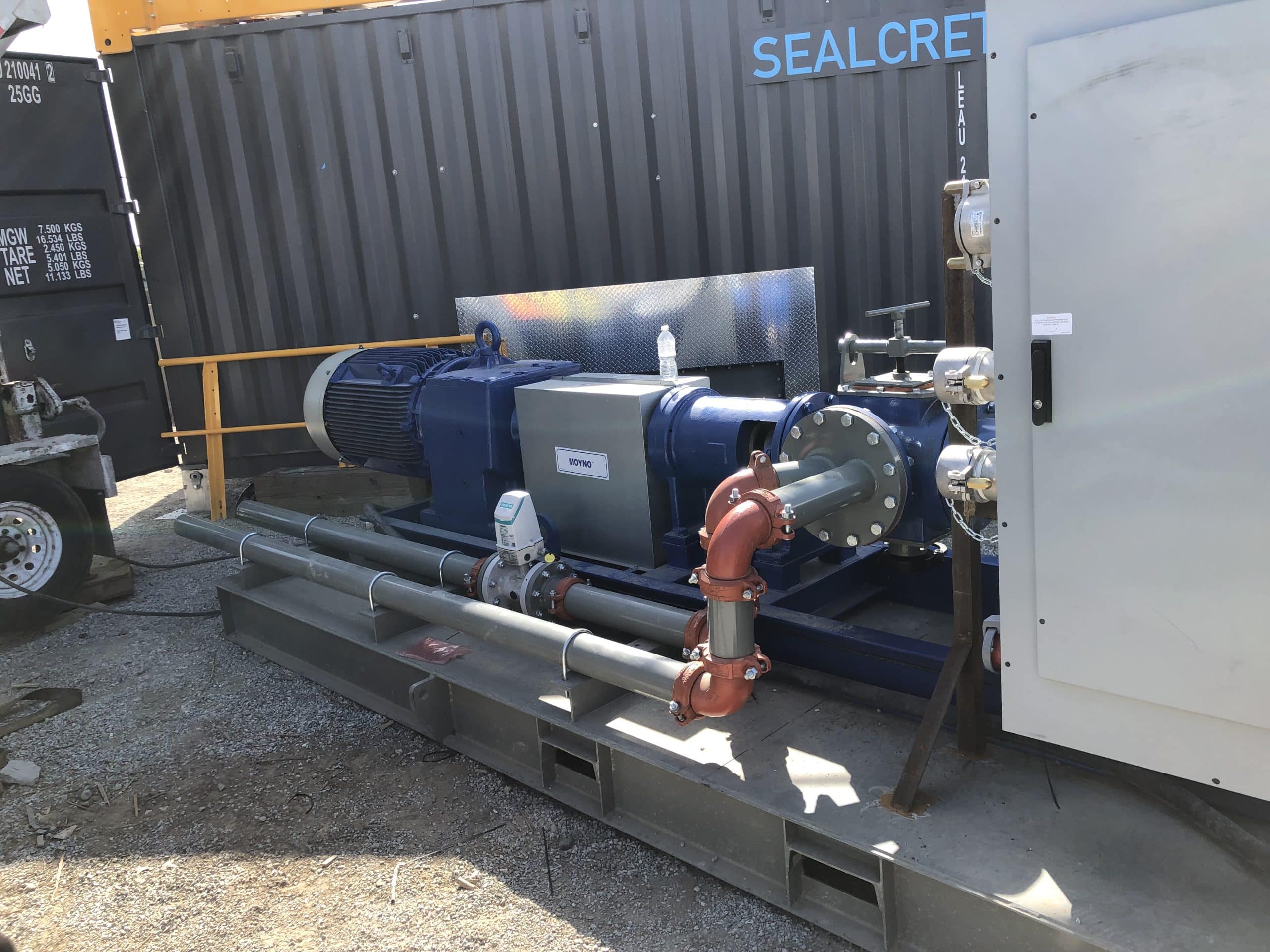
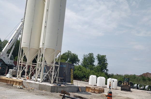
Starting the week off with a new installation! What do you get when you mix a SealCrete with a foam generating system and pump…? A cellular grout plant! More info on the Simem SealCrete here:

June 3, 2022
Education is a staple core value here at Simem. We are proud to give our time to teach the next generation and help them build the skills needed to keep the industry focused on cutting-edge technologies! In Aug, Phil Antunes will lead a short course on Backfill Grouting at the Colorado school of mines in Golden, Co.
More info and registration can be found here: Grouting and Ground Improvement Course

April 22, 2022
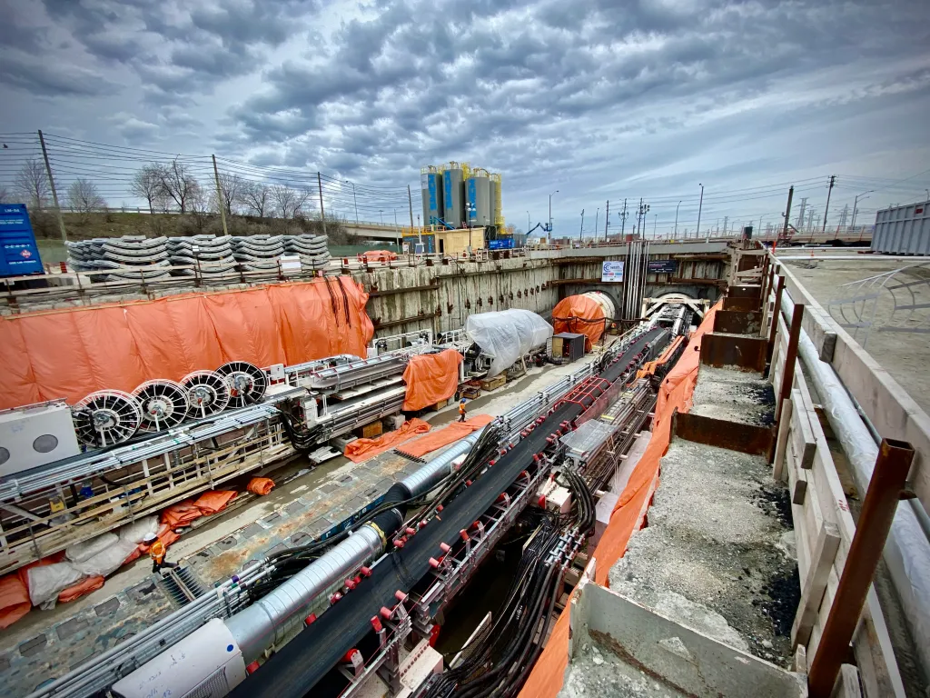
We here at Simem Underground are thrilled to be part of Canadian history’s most extensive subway expansion program! Click the link and see an amazing 10-week timelapse video of the setup featuring two Simem grout plants, a Simem pumping system, and Six Simem silos.
Full article here: Tunnelling starts on the Eglinton Crosstown West Extension
April 19, 2022
About the job
Role and Responsibilities:
Design mechanical and electromechanical products and systems by developing and testing specifications and methods, in cooperation with the electrical engineering department and customers to ensure an optimal design of the final project or product. The mechanical engineer will define product specifications, develop conceptual and final design solutions, manage and coordinate project activities, support existing product offerings, and perform testing/analysis of new and existing products.
Essential Job Results:
• Lead in preparation of product definitions and specifications.
• Participate in mechanical product design including product specifications, material selection, CAD design, and
detailed product drawings.
• Design, implement and test new products to achieve desired features and specifications.
• Document designs for product support and efficient development of successive product generations.
• Design to release to production, interface effectively with production department during manufacturing process.
• Creation of maintenance manuals and data sheets; Fulfillment of data sheets.
• Provides mechanical design information by answering questions and requests.
• Estimates material, construction, and labor costs as well as project timescales.
• Coordinate quality control on projects. Check components for dimensions, fit/finish and quality.
• Assist in ongoing R&D of prospective product lines.
• Ensures projects meet mechanical and construction safety regulations
• Maintains product and company reputation by complying with federal and local regulations.
• Maintains professional and technical knowledge by attending educational workshops; reviewing professional publications; establishing personal networks; participating in professional societies
• Contributes to the team effort by supporting the business as directed.
Requirements:
• 3D modelling experience: Inventor preferred or Solidworks
• Familiar with process design (not requirement)
• Experience in interfacing with production staff and process.
• Willing to travel for work
• On-site work required
• Industry experience/familiarity with Mining and Civil projects
• 3-5 years experience
• Excellent teamworking and people skills
• A comprehensive understanding of mechanical safety regulations
• Must work well under deadlines and have excellent problem-solving skills.
• A bachelor’s degree in mechanical engineering, Professional Engineer (PE) preferred.
OTHER
Job Details
Please send your CV for consideration to:
SIMEM is an equal opportunity employer and considers qualified applicants for employment without regard to sex, race, color, religion, ethnic or national origin, gender, sexual orientation, gender identity or expression, age, pregnancy, leave status, disability, veteran status, genetic information and/or any other characteristic or status protected by law.
April 7, 2022
Conquering Every Mining Plant Challenge with Simem Underground!
“In this episode, we chat with Simem Underground Solutions who design, engineer, and manufacture site-ready CRF/CAF, Paste Backfill, Shotcrete, and Slurry plants for on-surface and underground mining operations worldwide.”
Listen to the full episode here: DIG DEEP – The MINING PODCAST

March 11, 2022
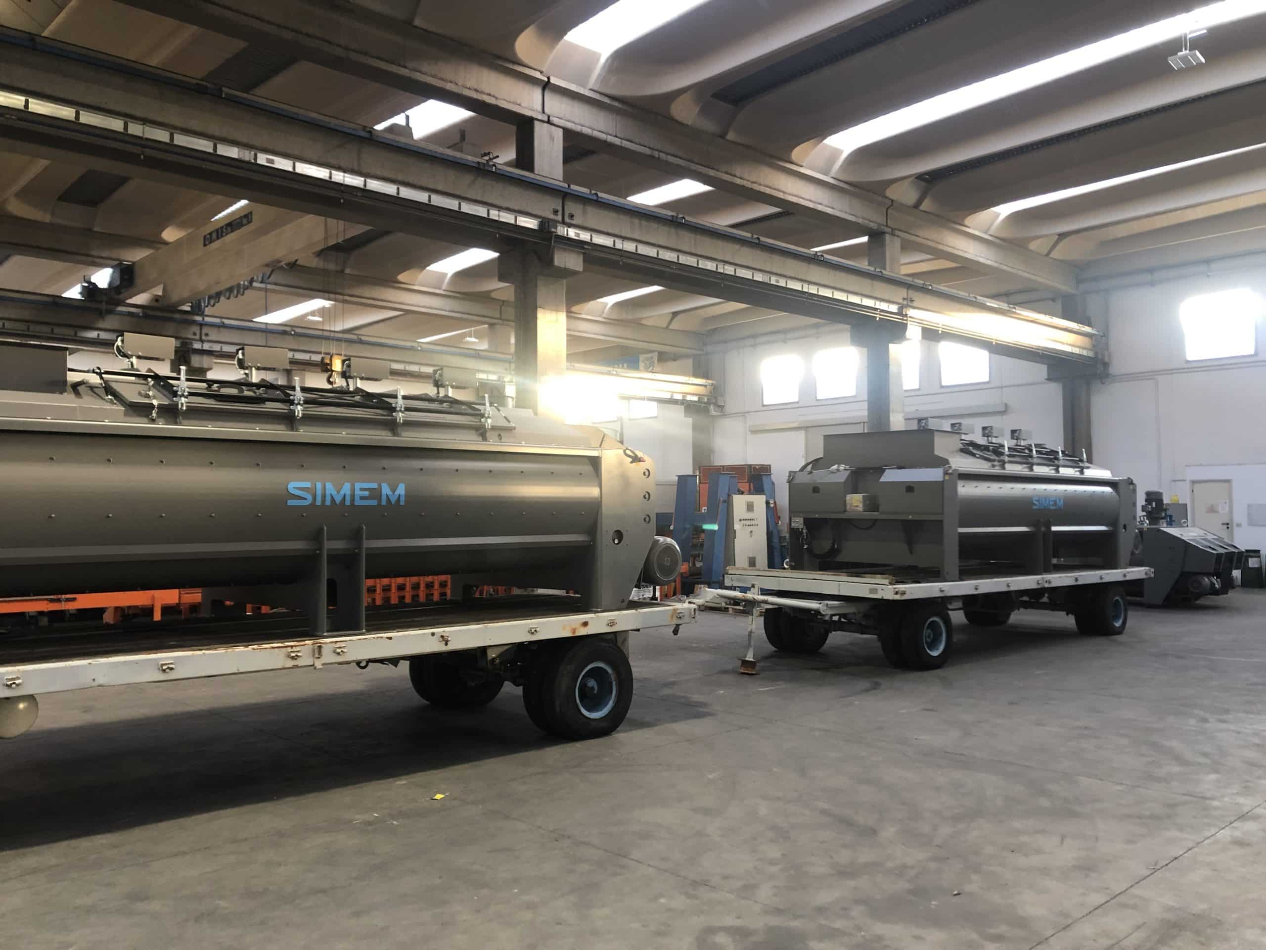
When a job calls for something outside of a standard product, we make it happen. So two custom-designed MDC paste mixers are heading to their new home. We are excited to share more about this fantastic project as it comes together in the coming months.
What can SIMEM do for you? Contact us here: here.
February 1, 2022
October 20, 2021
Simem Twin-shaft mixers – a market benchmark thanks to 40 years and thousands of units manufactured to serve the global demand for concrete production.
The next generation of SIMEM mixers has arrived and we welcome the RHYNO
Simem, known for quality and unquestioned reliability. The RHYNO twin shaft mixer boasts a robust design, user friendly paddle adjustment, and DYNA-FLOW mixing action. This prescribed combination of engineered features extends the lowest maintenance cost per cubic yard, or cubic meter, of concrete produced.
Let’s talk about your next project.

RHYNO twin shaft mixers are lined with stud-mounted high wear resistance liners. RHYNO paddles and arms are bolted to the twin horizontal shafts. The bolt on arm design allows for a various paddle positions to accommodate a variety of mix designs and ease of paddle adjustment.
This method and engineering technology also provides an optimized mixing result.
Cutting edge Fluid-Dynamic simulation was used to support the design of paddle profiles and arm connection points. In partnership with a leading Italian University, mixing action was optimized to deliver further mixing advantages for concrete producers, which include:

RHYNO twin shaft mixers range from 1 yd3 to 3.5 yd3 of compacted concrete output.
RHYNO twin shaft mixers produce best in class conventional, SCC, RCC, and dry-cast concrete.

Simem mixers are equipped with high efficiency planetary type gearboxes, boasting a mechanical efficiency of up to 94%.
Integrated oil cooling systems ensure a correct operational temperature to promote a healthy gearbox life and help reduce maintenance costs.

All Simem mixers are equipped with engineered labyrinth mixer shaft seals.
Seals are constantly lubricated by an electrically driven grease pump with sensors to safeguard for proper functioning.

Simem exclusively designed orbital high pressure rotating wash heads are self-retracting and driven by an independent gearbox and electric motor.
Mixers are treated to a near 3,000 psi cleaning, leaving minimum residual concrete remains in the mixer tank.

| MODEL | 1501 | 2001 | 2501 |
| Dry filling capacity m3/cy | 1.5/2.0 | 2/2.6 | 2.5/3.3 |
| Compacted concrete m3/cy | 1/1.3 | 1.7/2.22 | 2.5/3.27 |
| Output – wet concrete kg/lb | 2,400/5,280 | 3,120/6,860 | 4,080/8,980 |
| Max aggregates size mm/in* | 80/3 | 80/3 | 80/3 |
| Mixing Motors kW/hp | 2×18.5/25 | 2×22/30 | 2×30/40 |
August 25, 2021
Gaining accreditations demonstrates our commitment to the responsible supply of high-performing equipment solutions worldwide. Recently, we proudly received our BuildingConfidence Accreditation from Achilles.
BuildingConfidence is the construction standard proving certification to Safety Schemes in Procurement (SSIP) and the Common Assessment Standard (CAS), putting the community at the forefront of standards in the UK.
Simem Underground Solutions’ supplier accreditation demonstrates compliance with the Common Assessment Standard (Desktop), UK Health & Safety Legislation, and CDM Regulations 2015.

June 14, 2021
Originally published in MINEFILL 2020-2021
Leslie Correia & Brent Cothill
Paterson & Cooke Canada Inc
Phil Antunes P.E., P.Eng.
Simem Underground Solutions Inc
Sean James
Rearden Metals & Mining
A zinc, copper and lead mine located in Canada has recently restarted operations after several years under care and maintenance. The mine had an existing paste plant that was historically used for surface tailings deposition. The existing paste plant was overhauled and retrofitted to be able to handle full plant tailings and produce cemented pastefill that will achieve the required target strengths underground. In this case study, the various design challenges faced and lessons learned are documented which led to the successful retrofit of the paste plant in 2019.
Keywords: Construction, Design, Retrofit, Paste
After an improvement in base metal commodity prices during 2017, a zinc, copper and lead mine located in Canada has restarted operations after a hiatus caused by unfavourable market conditions and high operating costs. Various operating scenarios were considered, but ultimately, a revised mine plan was developed incorporating paste backfill.
Historically, backfill at the mine was produced at an existing hydraulic fill plant using classified tailings. The fines portion of the tailings stream was sent to an existing paste plant used for surface tailings deposition only.
The mine’s capability to store tailings on site is limited. One of the requirements for mine restart-up was to maximise the placed density of tailings used as backfill and disposed on the tailings storage facility (TSF) by using full plant tailings. The mine design, therefore, had a longer-term plan that relied on pastefill and phased out hydraulic fill. Using the pastefill has an additional benefit of achieving a more consistent backfill product with better cycle times.
Several different plant design options were considered, each derived from the existing backfill facilities on-site. Analysis of the hydraulic fill plant showed that this plant was not capable of handling full plant tailings required to produce paste. Feasible options identified included repurposing the existing paste plant with a new internal configuration or building a new paste plant using a combination of new and existing equipment. Inspection of the paste plant and subsequent trade-off studies demonstrated that the existing paste plant was in fair condition and held enough value leading in favour of the retrofit upgrade.
This paper documents the design and construction challenges associated with overhauling and retrofitting the existing paste plant providing a summary of lessons learnt.
2 PROCESS DESCRIPTION OF EXISTING PASTE PLANT FACILITY
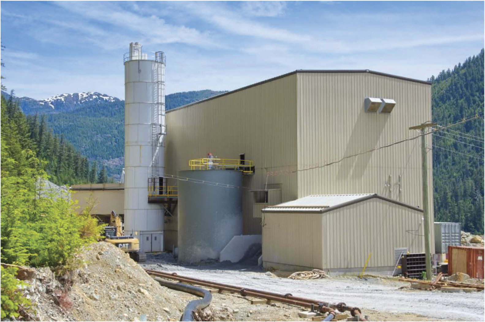
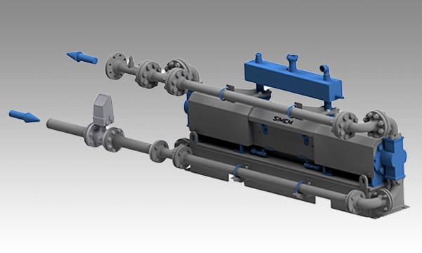
The existing paste plant was historically used to dewater tailings slimes before deposition on the TSF. The paste plant included the following major pieces of equipment: A cyclone circuit, a high compression thickener, a single vacuum disc filter, a custom-made twin shaft mixer and two positive displacement pumps. A simplified flow sheet of the existing paste plant is provided in Figure 1. Figure 2 provides a 3D model of the existing internal equipment and structure within the paste plant building.
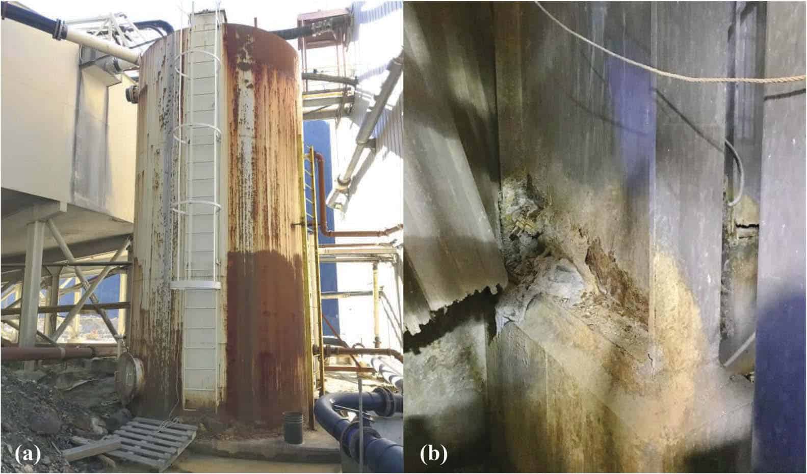
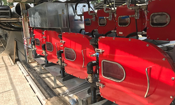
Tailings from the mill reports to a cyclone circuit located inside the paste plant (Figure 3a). The cyclone underflow is pumped to the hydraulic fill plant and the cyclone overflow is transferred to a 25 m diameter high compression thickener (Figure 3b). Thickened tailings (~60%m) is transferred directly to a single vacuum disc filter unit (Figure 3a) to achieve a cake moisture content of 22 to 26%. The filtration unit is a GL&V 3.2 m unit equipped with 12 discs and has a total filtration area of 173 m².
The filtered tailings and trim water were fed to a custom-made continuous twin-shaft mixer (Figure 3c). The discharge from the mixer was via an overflow which allowed paste to be gravity fed to one of two 100 bar rated Schwing KSP 110 V (HD) L (one duty/one standby) piston positive displacement pumps (Figure 3d). The piston pumps distributed the uncemented paste to the TSF.
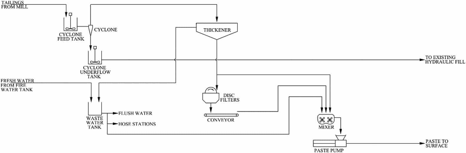
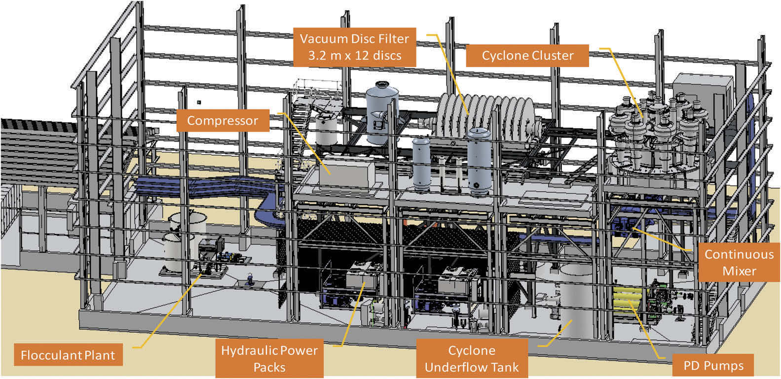
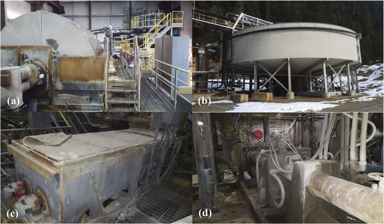
Figure 3. Photos of existing paste plant, (a) view of disc filter (left) and cyclones (right); (b) view of thickener adjacent to paste plant; (c) continuous mixer; (d) positive displacement pumps.
3 MECHANICAL UPGRADE/RETROFIT
The existing paste plant was redesigned to produce a cemented paste backfill product to support the mining activities while matching the overall mill utilization of 85 to 92%. A comparison between the existing paste plant 3D model and the as built 3D model complete with the new retrofits is presented in Figure 4.
3.1 Cyclone circuit
The paste plant previously processed the fines fraction of tailings only. The retrofitted paste plant would use the total tailings stream and would bypass the cyclone circuit. The cyclone cluster was therefore removed to allow space for a new dust collector. Furthermore, the cyclone underflow tank and pumps were also removed to allow space for the relocation of the existing flocculant plant.
3.2 Thickener and process water tank
Remediation of both the thickener and process water tank were relatively well scoped and properly understood, however, difficulties arose during the clean-up of these items. The thickener overflow launder was full to overflowing with tailings fines, while the bottom of the thickener contained a significant bed of very dense material left behind, estimated to be about a metre thick towards the centre. Cleaning of these items required a significant amount of work using a vacuum truck, pressure washers, and labourers manually shovelling tailings in order to remove all of the compacted material. Due to escalating costs a decision was made to only remove enough material from the bottom of the thickener to perform a proper inspection of the rake and drive mechanism from within the tank. Once the thickener was refilled with water the rake was restated and used to carefully remove the thickener bed by incrementally lowering it until the torque readings stabilized and then repeat.
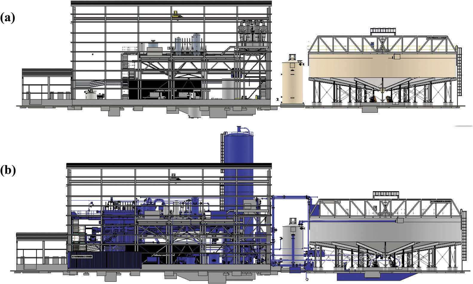
Figure 4. Comparison between (a) Existing 3D model and (b) As built 3D model (new equipment shown as blue).
The process water tank had substantial corrosion and required a more involved remediation or complete replacement. The tank was opened to facilitate sandblasting and painting of the interior. An initial inspection of the tank interior was not done as all the inspection hatches were inoperable due to corrosion. As such, once the process water tank was opened, it was discovered that it was more than half full of tailings. Again, the use of a vacuum truck, pressure washers and labourers were employed to empty the tank.
While these cleaning activities were seemingly small and partly anticipated, the magnitude of the time required to perform the work and the corresponding costs were substantial and noteworthy.
3.3 Thickener feed system
The only major modifications to the thickener were made to the feed system. The existing feed system incorporated a feed tank mounted near the centre of the bridge. Nine feed pipes reported to the tank, some continuous operation, some redundant. The discharge outlet nozzle of the feed tank was vertical and fed through a series of 45° elbows into the feedwell. This arrangement was replaced with a single common feed box mounted on the outside periphery of the thickener tank with one common feed pipe feeding tangentially into the feedwell. This will provide a homogeneous feed that can be injected without air or disturbing the settled bed that lies underneath the feedwell discharge.
The existing feedwell itself was a closed bottom design, 4 m in diameter and extended ~2 m in depth. It had a choked lower section fitted with a deflector cone and cone scraper. The deflector cone gap was fixed and did not allow for any changes in throughput. This configuration often lead to short circuiting of the coarse material within the feedwell creating a beach on the thickener tank floor (usually located either opposite to the feed entry point or further around, depending on the particle size). The beach caused an unbalanced load on the rake mechanism, torque spikes on the drive and intermittent slugs of coarse material to pass through the underflow nozzles. The feedwell was replaced with a correctly sized unit providing more efficient and newer technology that prevents short circuiting. This significantly improved the capture of fines and uniform distribution of solids into the thickener tank.
3.4 Vacuum disc filters
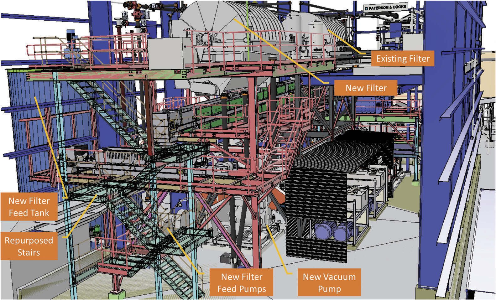
The existing vacuum disc filter was refurbished with a second 3.2 m dia. x 12 disc vacuum disc filter added to provide redundancy and/or boost the solids production capacity if required. The new filter was orientated in a left-hand configuration to compliment the right-hand configuration of the existing filter. This allowed both filtrate receivers and snap air tanks to be orientated in between the two disc filters optimizing the space available.
The support structure was extended to support the second filter (Figure 5 & 6). The existing flocculant plant was moved to where the cyclone underflow tank was located previously while the existing west staircase was moved over against the west side of the building. The new structure allows top access to the filter feed tank and agitator.
3.5 Filter feed tank and pumps
The existing thickener underflow pumping system fed thickened tailings directly into the existing vacuum disc filter boot. As part of the retrofit, an agitated filter feed tank was introduced to provide a two hour surge capacity for the vacuum disc filters and allow for proper control of the slurry extraction density out of the thickener. The filter feed tank was located on the outside of the paste plant building with the filter feed pumps located directly underneath new vacuum disc filter inside the building. The filter feed pumps maintain a ring main header from which the existing and new filter boots are fed. A bypass on the ring main also allows trim slurry to be introduced directly into the mixer operation, thereby reducing the load on the filters.
3.6 Conveyors
The existing filter cake conveyor was replaced due to its poor condition and increased length required to serve both filters. Due to the limited elevation available between the filters and the new mixer, the belt angle of the main conveyor was set at 5°. The new main conveyor was also equipped with a reversing function allowing filtered tailings to be transported through the side of the plant. This will allow the mill to continue producing tailings in an upset condition where equipment/piping downstream of the mixer fail. In reverse, the main conveyor would transfer filter cake onto a secondary conveyor which in turn transfers the filter cake onto a stockpile allowing trucks to haul the filter cake to the TSF on a short-term basis.
3.7 Continuous mixer
During on-site visits, the paste produced by the existing mixer was witnessed to be full of lumps (filter cake). The filter had a very short residence time (~30 s) and was inadequate to ensure quality backfill production due to low energy input. It was also unlikely that the mixer would be able to adequately disperse the binder and produce a high-quality paste. A low-profile twin-shaft mixer was installed with a residence time of ~2.5 minutes. The new mixer was installed on a new lower steel platform.
3.8 PD pumps
Upon inspection of the two existing piston pumps, it was found that these pumps would need to be replaced due to the poor condition they were in. The associated hydraulic power packs were refurbished and reused. The new PD pumps were moved to align with a new paste hopper.
3.9 Cement system
As the existing paste plant was constructed for surface deposition only, a new cement system was added to the paste plant to allow binder to be fed into the mixer. This included a 168 m³ binder silo, rotary feeder, weigh-belt feeder and screw conveyor.
Initially, it was considered to locate the cement silo on the road side of the plant. However, it was concluded that there may be interference with mine traffic and that the required screw conveyor lengths would be such that it would impede the lifting bay near the mixer. A location behind the paste plant was selected instead that resulted in a short conveyance inside the building to the mixer. To feed the silo, cement trucks park in a lay-by area and transfer cement via tubing across the paste plant to the silo.
Construction of the binder silo was challenging. A bolt up silo was ideal for the limited site access but the tight work envelope made is difficult to take advantage of having a larger crew assembling rings in parallel. This in turn used up more crane stand-by hours waiting on the next ring to be placed.
Another take-away from this is to understand the contractor’s capabilities to perform specific specialized work. Construction of a bolt-up silo requires specialized installation expertise in order to get the greatest efficiency out of the construction. The incumbent contractor could rarely dedicate itself to silo construction due to shifting priorities and this resulted in substantial project schedule delays.
3.10 Piping and valves
Much of the piping and valving in the plant was installed as new with the exception of some runs of gland water and compressed air piping dedicated to existing equipment.
4 CIVIL/STRUCTURAL UPGRADE/RETROFIT
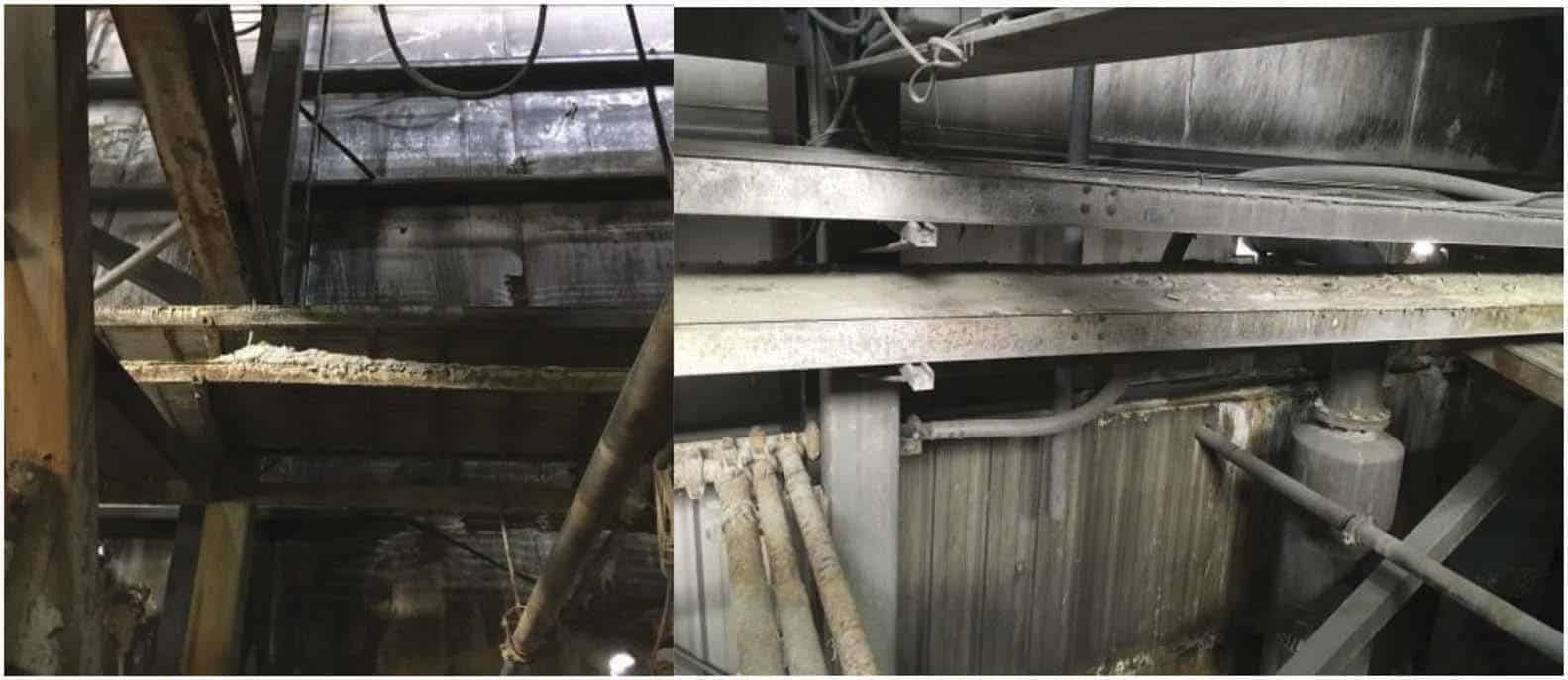
Initial inspections were conducted to determine the condition of the structure, equipment and tanks that would be reused in the retrofit. While most of the structure was in good condition, any steel that had been in contact with tailings was corroded and required remediation (Figure 7). Fortunately, the equipment and structure with the most significant corrosion and those that had seen resourceful repairs by plant staff were to anyway be replaced by new equipment and structural steel as part of the retrofit. These included the filter cake conveyor, paste mixer and mixer platform structures. The remaining structural members that had minor contact with tailings spillage were sand blasted or wheel abraded in place and coated with a two-part epoxy to protect from future exposure.
4.1 Building code
The original paste plant engineering was completed in 2002 using the 1998 British Columbia Building Code while the 2012 British Columbia Building code was required for the plant upgrades. The 2012 code has seen substantial amendments including the seismic design requirements.
The initial structural design approach for the retrofit was to maintain isolation between the original and new equipment structures to minimize upgrades required to the original structures. However, due to the building envelope size, process flow and equipment layout, the resulting structural load paths required certain upgrades to the existing structure as well as an over design of the new structural components to compensate for the insufficient seismic resistance of the existing.
4.2 Soil/Foundation conditions
Perhaps the most challenging part of the structural design was related to foundation conditions and the resulting impacts to the surrounding building elements. This specifically applied to the binder silo.
The existing structure and layout of the process equipment favoured a design that elevated the silo outlet to allow the binder screw conveyor to feed horizontally into the mixer. The specification required 250 tonnes of live binder storage. The procured silo had a 4.67 m diameter, an outlet height at 12.8 m and a silo eave height of ~22.5 m which resulted in a centre of gravity at 16 m. In addition, through the procurement process, a skirted silo design was selected rather than a custom structural platform for economic and layout reasons.
The silo layout was based on geotechnical assumptions before the commencement of the detailed design and the allowable soil loads could be determined. When past geotechnical data and reports were reviewed, it was found that the existing plant subgrade was largely fill material and the existing building and equipment footings were placed on dynamically compacted subgrade. Furthermore, the densification required for construction was performed only in areas where the footings were constructed in 2002 and the condition of the surrounding grade was unknown. A follow-up geotechnical investigation confirmed that the soils were composed of “mixed organics, mine waste rock, and other mine waste materials” to a depth of 3.3 m and limited the allowable soil bearing capacity to 75 kPa.
As per the geotechnical findings and resultant loads, calculations required a raft footing of 10.7 m by 10.2 m to resist to overturning moment of the relatively tall silo and high load. The site layout, however, set the distance from the centreline of the silo to the outside of the existing building to only 3.345 m. This accordingly required that the silo foundation to encroach into the building by over 2 m via concrete and rebar to tie into the structural steel supporting footings on the building’s interior. When the need for a large raft footing was determined, a design review was called to determine alternatives. Options reviewed included silo relocation, pile foundations and anchoring to a nearby rock slope. In the end, the raft footing design was retained which resulted in construction sequence modifications.
The results of the geotechnical assessment indicated that a novel approach would need to be taken during excavation in order to avoid undercutting the existing building footings. The process specified by the geotechnical team called for excavating narrow channels, roughly a metre in width, to the specified elevation in order to avoid unloading the footings that the building columns were situated on. Engineered material was then backfilled into the cavity in 300 mm lifts and compacted with a hoe-pack until the final elevation at which the concrete would be formed and poured on was reached. Once an excavation was complete, the excavator would move over and begin the next cut until the full width of the foundation was excavated and backfilled. This was a time consuming and costly exercise that had to be carefully supervised and regularly surveyed. Normally a bulk excavation would be sufficient for such work.
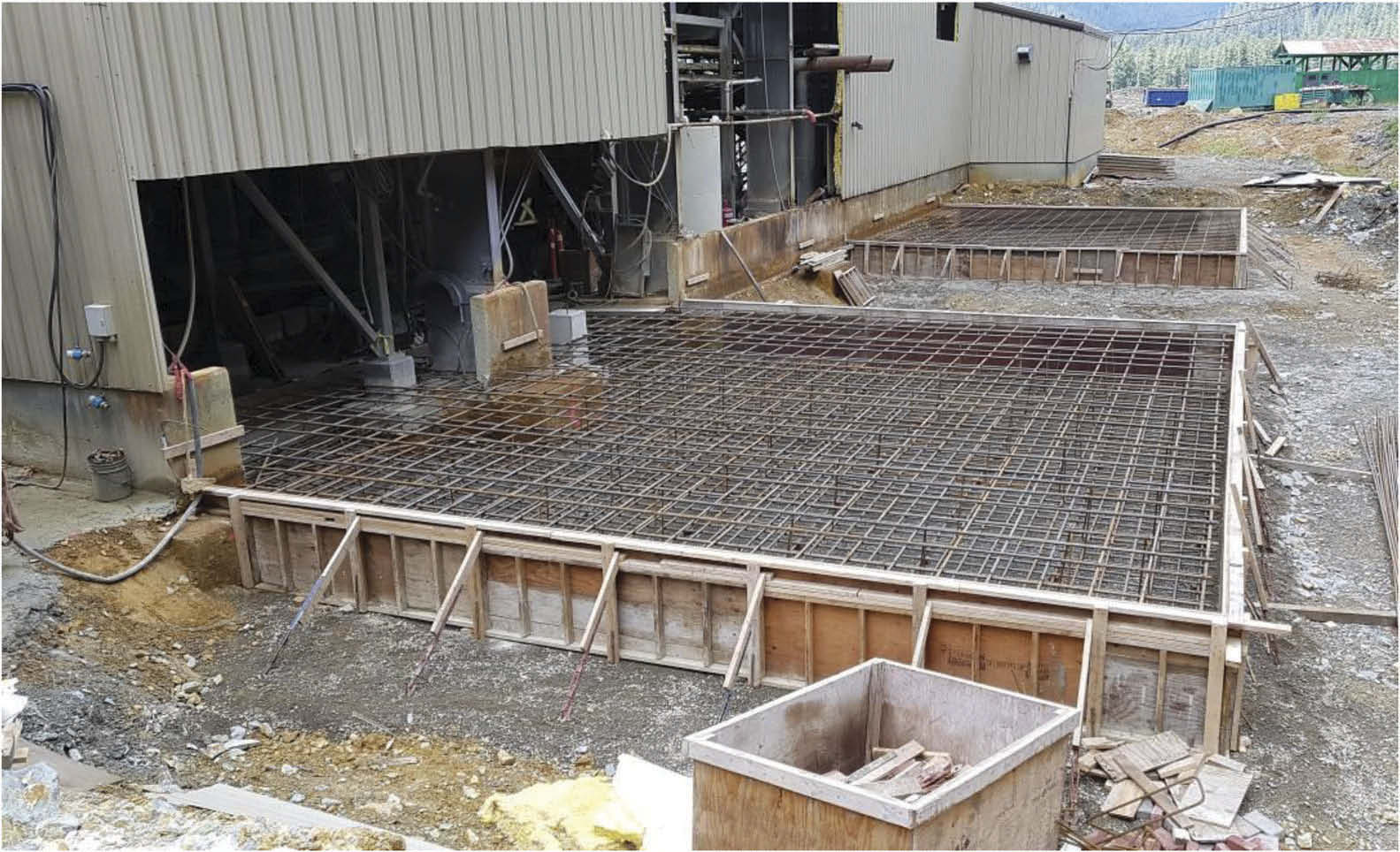
The design challenges that were faced with the binder silo foundation also created additional construction challenges. In order to properly construct the foundation, the stem wall to the building had to be cut out and removed and the floor in the north east corner of the plant was saw-cut and removed. Rebar for the silo foundation was specified as Ø25 mm bar, layered at ~200 mm spacings. To effectively tie the foundation into the interior structural footings, it was necessary to extend the bar into the building and dowel into the existing concrete before pouring new concrete around it (Figure 8).
It was essential that the concrete forming the binder silo foundation was isolated from the building footings while still being fully tied into the upgraded structural steel supporting footings. This was done to avoid complex interactions with the new footings, potential problems due to differential settlement and the need to update to current building and seismic codes.
An additional complication was that approximately three times as many anchor bolts were required for the silo to comply to the seismic regulations of the code. This configuration was not provided in the original vendor issued for construction (IFC) drawings and, as such, was unknown at the time of the foundation design. Resultantly, no consideration was given to anchor bolt locations in relation to rebar in the foundations. The contractor had an exceptionally difficult time drilling holes for anchor bolts as they continually intercepted rebar due to the tight bar spacing and large bar diameter. In hindsight, a better approach would have been to template and place embeds during the pour.
The filter feed tank foundation was less complex as it did not have to resist the same overturning forces and, with a wider base, had different load characteristics. However, the excavation requirements were largely the same and the same issues with anchor bolt placement was encountered.
4.3 Structural steel
A complete 3D model of the building and equipment was created during the design. The principle equipment components and main structural members were well accounted for and accurately depicted in the model. However, some existing ancillary items, such as process piping, equipment components, cable tray routing and building tension bracing, were not all accounted for or correctly modelled. As such, the entire building and contained equipment were photo logged and manually measured to create an accurate model.
There were several cases where items were inaccurately estimated and caused rework onsite due to interferences. While none of these had a direct impact on the critical path of the installation activities, they nonetheless impacted the cost of the work and ultimately caused some delays to the overall schedule.
One example case included a key load-carrying beam on the north side of the plant directly interfered with one of the primary building columns. Similarly, a load carrying beam interference was discovered on the conveyor deck. These example cases required a redesign, additional steel fabrication and additional installation time.
In another case, the interference of the disc filter access deck with the motor for the bay door was discovered. As part of the retrofit design, the existing 3 platform stair tower had to be translated westward by 10 m to allow for the insertion of the new disc filter support structure. The tower also required modification to allow the upper floor to be extended for access and maintenance. The model indicated that the modified deck and tower would be tight up against the west wall but the main overhead door access to the plant would remain clear. However, when the tower was moved and modified, it was discovered that the location of the door motor and track did not match the model even though the main plant overhead door was accounted for. As a result, main load bearing column carrying the upper deck had to be removed and the tower had to be modified, requiring a substantial redesign.
4.4 Cantilever staircase to access binder system
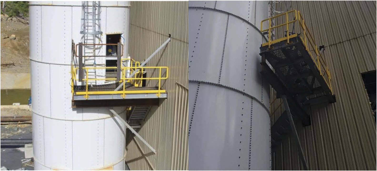
Once the silo foundation design was finalized, the necessary access bridge could be detailed to connect the interior mixer deck to the silo. The initial intention was for a short stair run and platform that would be attached to both ends; one to the silo and the other to the interior mixer deck. It was subsequently found that no provision for loads or attachments of a platform had been made on the skirted silo design. The access platform and staircase therefore needed to be completely supported from the mixer deck structure which required a creative design effort due to limited anchoring members being available. Furthermore, the cantilever platform required a 90° turn which needed to be incorporated into the support design.
The challenges associated with the design of the cantilevered access platform were realized because the precise location of the silo could not be predicted by the design team, partly because of the necessity to situate the base ring wherever the anchor bolts could be drilled around the rebar in the concrete. The resulting stair and platform (Figure 9) are functional although it required site modifications to limit the deflections and minimize the gap between the platform and silo entrance.
4.5 Overland pipe installation
Several challenges were encountered with the overland paste pipeline layout and installation. No as-built survey information was available at the time of design. The design layout of the overland pipeline was therefore indicative and, in order to account for various interferences in the pipeline corridor, specified as “field fit” to the contractor’s discretion.
A “field-fit” slope was indicated on the pipe run between the plant and the primary switchover station. Sloped pipe supports were designed which could be adjusted to suit the in-situ slope requirements. Due to the way the curve switch-over spools were oriented, this slope could vary considerably without causing any layout issues. The pipe runs both east (to a borehole) and west (to a portal) from the same switch-over station and had no specification for sloped pipe brackets even though both runs were on a slight slope (<2%). This was handled by adjusting the drop spool of the switch-over station and then using grout packs to make up the gaps under the pipe supports.
As a survey laid out the pipe supports required along the retaining wall at the portal entrance, it was noted that the centreline for the pipe would be a little over a metre away from the portal retaining wall. However, the design specified the pipe centreline as being approximately 0.3 metres away from the concrete. This off-set was necessary in order to tie the paste pipeline from surface in with the underground installation which was already in place. An excavation was done adjacent to the wall and it was discovered that the portal retaining wall footing would also be in the way of the planned pipe support. Resultantly, a bespoke pipe support had to be designed that was doweled into the retaining wall footing.
5 ELECTRICAL UPGRADE/RETROFIT
The electrical updates required to support the retrofit required an additional 575 kW to the existing electrical load and approximately 330 control inputs and outputs in addition to various protocoled communication links with field devices.
5.1 Existing cables and hardware
The inspection of the cable runs revealed that the cable trays were both overloaded and covered in tailings. Large sections of cable trays were replaced due to poor condition arising from corrosion (Figure 10). Electrical cabling suffered the same fate with large quantities of it being replaced due to cracked sheathing and great difficulties in identifying which cables were in good conditions and which not. The poor condition of the cables and trays in the plant ended up being significant both in terms of cost and having a negative impact on the project schedule.
5.2 MCC
The Mine specifications required that Motor Control Centre (MCC) were NEMA rated which requires an isolated enclosure, or “bucket” for each motor. Repurposing unused buckets in the existing MCC was problematic as many items were missing or had been modified historically. In addition, the design had to rely on outdated single line diagrams and cabinet layouts. Buckets were, however, repaired and utilized where possible to reduce the required size of the new MCC. Even so, the new equipment increased the plant motor count by over 45 in total and the new MCC required to house all this switch gear was over 6 m long in addition to several subpanels. Several MCC layouts and locations were considered including locating the new MCC in the plant area underneath the relocated stair tower which would separate it from the existing electrical room. This would, however, have complicated the control wiring and communications while requiring an upgrade to an IP65 enclosure. The existing electrical room was therefore reorganized to accommodate all the new switch gear and still meet code clearance requirements.
5.3 Automation hardware and software
The mine had planned to utilize the existing PLC and hardware with the addition of an expansion I/O to accommodate the new equipment. The Wonderware SCADA and HMI system were also to be reworked to minimize impact to the existing automation. After a thorough review it was found that the existing Quantum PLC had been obsolete and while service and repair would be available in the near future, new components were only available through 3rd party vendors who had excess inventory. As the plant life was scheduled until 2028, there was a concern that the existing automation hardware would not support the operation. In addition to the availability and support of the automation hardware, the PLC would also struggle to accomplish the required scan times. Lastly, the communication required to incorporate new vendor PLCs for components like the paste pumps which were supplied with modern PLCs was also of concern.
Once all these concerns were presented, it was agreed that the automation package required an upgrade to modern components, software and operating systems to provide longevity and scalability. Up to this time, the automation and interface programming were impacting both schedule and costs. An alternative solution was made to use the existing I/O’s and that only new components added to the system would require new I/O points. The existing PLC was replaced with a communication module and the associated I/O rack would become a slave rack to the new PLC. There was still a risk of having obsolete I/O cards in the existing rack, but these could still be purchased and kept as spares. Importantly, the CPU and communication modules were new and expected to be available and supported well past the life of the plant.
6 BUDGET
The initial budget allocated to the project was sufficient based on reasonable expectations of costs garnered from past projects in conjunction with the scale of the work required. It did, however, suffer from some challenges along the way.
The project budget was based on a pre-feasibility design and fairly recent cost estimates. However, a stifled commodities/trade environment placed pressure on this estimate. During the bidding period, a sudden uptick in available local work caused rising labour costs while ongoing international tariff negotiations caused steel prices to rise, thereby influencing costs of both structural steel and piping. In an effort to control these costs, the project was submitted to tender for a second time to attempt a reduced construction costs through more robust competition. Concessions were made on long lead orders (e.g. piping) to reduce costs in exchange for higher risk on delivery and/or compromises on other commercial terms.
A second item that influenced the budget was the remote location of the project that seemed to be a unique area where potential contractor companies seem reluctant to mobilize. Adding to this, although the project budget was significant, the available construction budget seemed to fall below the threshold for project work that major mining contractors were willing to undertake. Correspondingly, many of the local construction firms were simply not large enough or properly equipped to take on the work. This left very few suitors and created a near monopoly for the very few companies that were both willing to take the work and large enough to be successful on the project. This made getting truly competitive bids very challenging. In hindsight, it would have been wise to make the project more financially attractive by including other parts of the scope in the tender package in an effort to attract some of the larger competitors.
The third key budget item was directly associated with the installation of the paste pipelines and associated infrastructure in the underground mine. Much of the mine was in adequate condition to accept paste line installation with little of the mine rehabilitation performed in advanced. The areas for the paste pipeline installation were beset with a variety of issues including bad ground, redundant or old services, failing services, blockages due to hydraulic fill spills, water, etc. While rehabilitating the mine should not be included in the paste line installation scope, costs should have been allowed for the reconfiguration of the existing services in order to accommodate the paste lines.
Finally, the budget did not make allowance for issues associated with new construction on poor foundation soils in an active seismic zone. Costs associated with upgrading structural foundations, technical excavation of fill materials around building footings, and two sizeable foundation pours in support of the filter feed tank and, the binder silo were categorically out of scope and not typical.
7 SCHEDULE
As with most retrofit projects, the paste plant refit had its fair share of scheduling challenges. The original restart schedule was aggressive as the mine endeavoured to get underway as soon as practicably possible in order to start generating revenues to off-set capital costs.
7.1 Long lead procurement
Initially, accountability for many of the mine’s restart projects, including the paste plant retrofit, was with one person. Resultantly, procurement of long lead items languished due to many competing priorities. Due to procurement delays, the principle vendor selection criteria was often the delivery schedule which resulted in price escalation and budget impact. In other cases, the agreed-on delivery date could not actually be met causing construction inefficiencies and associated increase in costs.
Additionally, delays on the procurement side introduced further delays on the detailed engineering side with the most noteworthy delays being to the civil and structural design. A notable example of this, was the binder silo (discussed earlier) as this required significant rework to both the structural members and the footings/foundations.
Allocating sufficient procuremnt time is important to maintain the budget as the owner has time to make informed decisions and to create competition between vendors for new business.
7.2 Design drawings & supply delays
Initially, design drawings were issued for tender with basic assumptions being made in respect to configuration of civils, structural, mechanical, and piping.
Civil and Structural IFC drawings were delayed due to redesign which stemmed primarily from the follow-up site geotechnical assessment. As discussed previously, this incurred significant rework for the concrete footings, the concrete volumes, rebar configuration, and structural steel configuration to access the binder silo.
The changes to the drawings resulted in approximately one month’s additional delay for steel fabrication and delivery. The delay closed the window on available floor time with the steel vendor and only part of the original scope was completed. To expedite the remainder of the work, the contractor fabricated a portion of the steel inventory in their own local shop.
While obtaining quotes for the new MCC a review of the drawings and specifications uncovered that the vendor had erroneously used the Issued for Tender drawings and not the IFC drawings when constructing the MCC configuration. While this was the vendor’s mismanagement of information, it highlights the importance of carefully managing drawing revisions and the critical importance of reviewing build specifications prior to committing to a purchase. The MCC took close to six months from order to delivery and since it was a critical path item, an incorrect build would have been an enormous setback.
7.3 Construction tender, bids, and award
As discussed earlier, the construction scope for this project was ultimately tendered twice. This was largely due to a lack of initial competitive bids but was also deemed necessary because of scope changes resulting from the design updates. The design updates, as has previously been noted, were directly related to both procurement delays and the consequential detailed engineering delays. As a result, the award for the construction contract was delayed by three months.
This schedule impact was further complicated with the addition of the structural steel supply to the construction contract. This was a long lead item and the contractor was forced to begin construction in parallel with structural steel deliveries. While there were activities that preceded the steel installation, it was a tight scheduling window and, as previously identified, there were challenges which caused significant delays.
7.4 Filter cake production
Towards the end of construction, the mine decided to run the mill which would require the paste plant to be operational to the extent that it could produce filter cake. In order to accommodate this, temporary electrical connections had to be made to the parts of the circuit required to produce filter cake. This included both conveyors, the original disc filter, process and gland water systems, the thickener, and the thickener underflow pumping system. This change in priorities caused a significant cost escalation and approximately two months delay to the schedule.
7.5 Underground pours
At the time that this paper was written, two successful underground paste pours have been completed. The mine is planning to ramp up production shortly to ensure the paste backfill adequately supports the current mine plan.
8 CONCLUSIONS
One of the allures of retrofitting an existing plant is to take advantage of the existing infrastructure. However, there is a risk to this approach and careful consideration should be given to what items can be practically salvaged.
Generally, the mechanical and piping aspects of the plant construction were relatively smooth. There were areas that caused difficulty though, and while the work was anticipated, the magnitude of that work during construction was somewhat underestimated. Most of the challenges experienced with construction of the plant were associated with the civil and structural packages. Key issues causing difficulties were poor foundation materials surrounding the plant, seismic requirements, design requirements for new binder silo, insufficient as-built information for the interior structural steel and unplanned structural interferences. Ultimately, the mine has been able to successfully conclude the paste plant retrofit job (Figure 11) with cemented paste being poured underground.
Minefill 2020-2021
Editors
Ferri Hassani
McGill University, Canada
Jan Palarski
Silesian University of Technology, Poland
Violetta Sokoła-Szewioła
Silesian University of Technology, Poland
Grzegorz Strozik
Silesian University of Technology, Poland
CRC Press/Balkema is an imprint of the Taylor & Francis Group, an informa business
© 2021 Copyright: Authors
Typeset by Integra Software Services Pvt. Ltd., Pondicherry, India
The Open Access version of this book, available at www.tandfebooks.com, has been made available under a Creative Commons Attribution-Non Commercial-No Derivatives 4.0 license.
Published by: CRC Press/Balkema
April 5, 2021
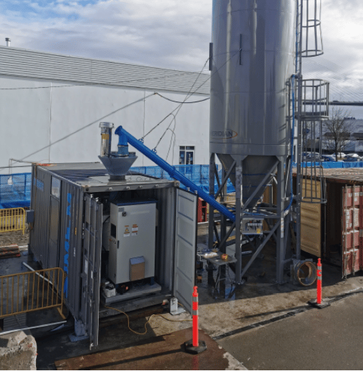
Fully commissioned OtterCrete for the Annacis Outfall Tunnel. Simem Underground colloidal mixing technology and a fully automated plant now producing grout in Vancouver, BC Canada for the Annacis Island Outfall Tunnel project.
March 3, 2021
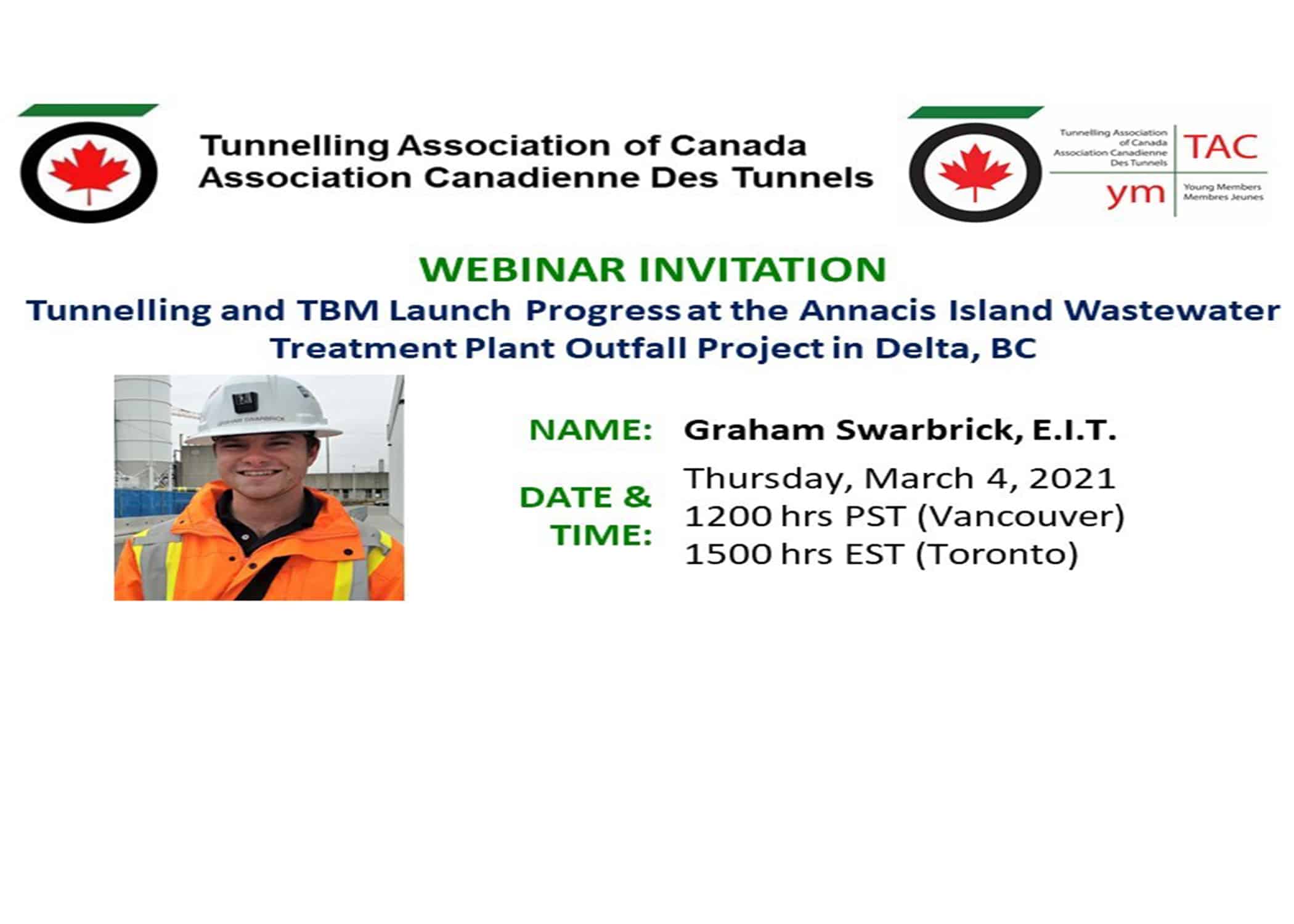
The Tunnelling Association of Canada presents the Young Members Group webinar on Thursday, March 4, 12:00 pm PST. The 2020 recipient of the TAC Undergraduate Scholarship, Graham Swarbrick will present Tunnelling and TBM Launch Progress at the Annacis Island Wastewater Treatment Plant Outfall Project in Delta, BC. SIMEM Underground commissioned an Ottercrete grout plant on this project.
Simem congratulates the achievements of young engineers and supports education to keep pushing boundaries in the field.
No advance registration is required – please use the webinar link (below) to access the meeting on the presentation day.
LINK: Webinar
February 9, 2021
SIMEM is proud to celebrate our 58th anniversary! On Feb 4th, 1963, our company was officially registered in Verona, Italy. We are happy to celebrate this bronze milestone and thank all the SIMEM family throughout the years.
January 13, 2021

More info here: CITY RAIL LINK
October 7, 2020
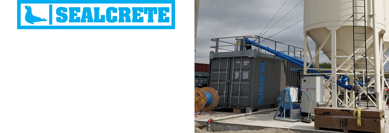
Major excavation for Ashbridge’s Bay Treatment Plant Outfall Project in Toronto, ON.
The tunnel boring of a seven-metre-diameter, 3.5-kilometre-long outfall underneath Lake Ontario from the Ashbridges Bay Treatment Plant in east-end Toronto is one of the largest and longest of its kind in Canada.
This project features the Simem Sealcrete
September 23, 2020
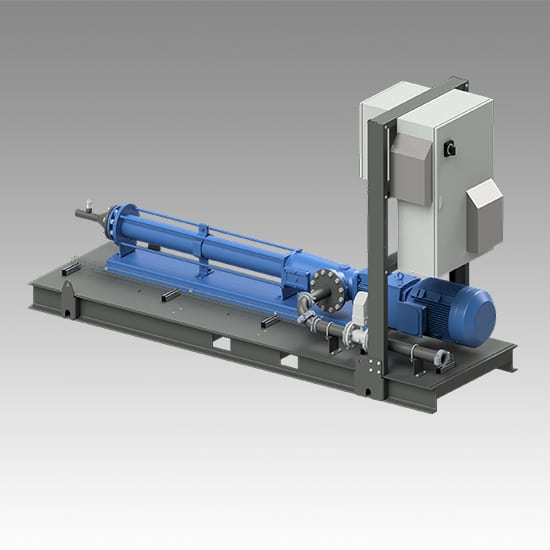
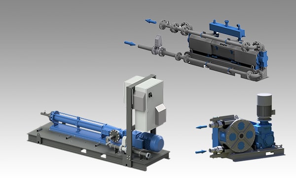
Pumping system design must consider many factors prior to operation. Matching a pumping solution for a specific project application requires extensive knowledge to ensure a pumping system performs as intended.
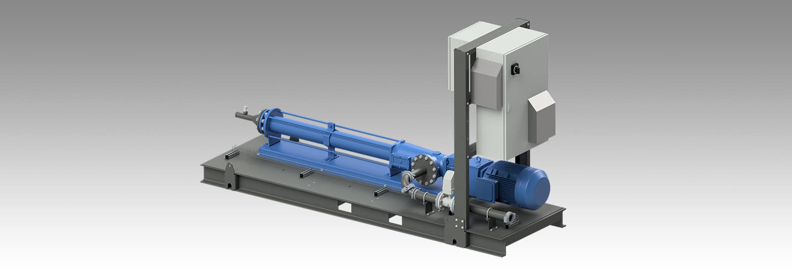
Simem Underground Solutions, and its decades of experience with long-distance pumping of bi-component grouts, cellular concrete, and hydrated bentonite, and cement slurries designs and assembles complete systems guaranteed to perform.
Systems are prepared for field connection as independent components, skid-mounted, or fully containerized. Applications for use in ,TBM’s, injection grouting, soil mixing, and slurry walls.
System types incorporate piston, peristaltic, progressive cavity, centrifugal, and air-diaphragm pumps. System come complete with associated power control units, instrumentation, and pipe cleaning assemblies.
Auxiliary Equipment Available
August 24, 2020

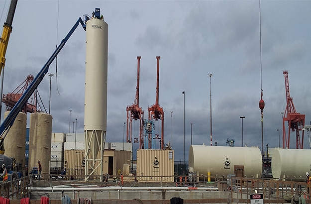
In July 2013 the world’s largest diameter tunneling machine began a historic journey beneath downtown Seattle. Its purpose: dig a tunnel to replace the State Route SR 99 Alaskan Way Viaduct, a double-deck highway that has spanned the downtown waterfront for more than half a century but was damaged in a 2001 earthquake.
Read more here:
May 29, 2020
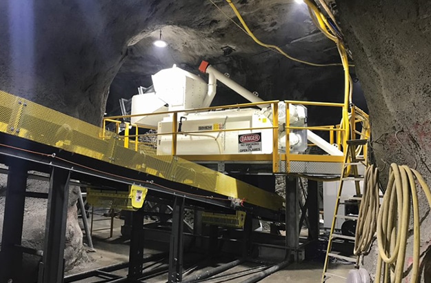
CLIENT: Stillwater Mining
SOLUTION: Modular CFR plant with MDC Rockfill mixer installed in Montana.
April 9, 2020
CLIENT: Anonymous Client
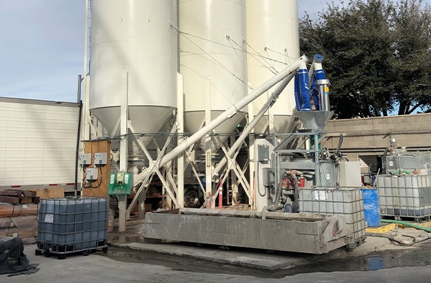
SOLUTION: OtterCrete plant with 1,500+ cycles of performance grout production for a Las Vegas tunneling project without downtime.