MobyMix

Compact, efficient, and easy to install – the MobyMix mobile batching plant is designed for easy set-up and effective results for your most important tunneling and mining projects.

Features

Built For Your Next Project

MobyMix is available in three different capacity sizes ranging from 21 yd3 to 65 yd3. The mixing support structure features patented foldable legs and is prepared to support cement, water, and additive dosing weighers.

MobyMix incorporates the Simem SUN planetary mixer, equipped with a planetary gearbox vertically secured to the electric driving motor, concentrating the transmission and driving system to the center of the mixing tank.

Easy Installation

Pre-wired electronics and pneumatic equipment allow for MobyMix to install faster than most other mixing plants.

The mixer support platform and aggregate modules are designed for transport with standard trucks. Simple leg positioning allows for easy self-unloading and self-erection by means of two hydraulic cylinders which lift the mixing unit into a working position.

Automated Operation

MobyMix utilizes our Simem@tic 3.0 NANO, an automation program that features a friendly interface to display all essential information about the plant for full operations control including loading, weighing, recipes, discharge, production lists, pending orders, and more.

Specifications

MODEL750 Duetto7501500
Aggregates compartments244
Mixer – PlanetarySUN 750SUN 750SUN 1500
Concrete output m³(cy)/hr15 (20)20 (28)40 (52)

Eagle

A compact, capable, and supremely transportable concrete batching plant designed for a wide variety of uses and projects within the tunneling and mining industries.

Features

Easy Transport & Assembly

All Eagle plants are pre-wired and pre-plumbed and they can be moved from site to site with standard trucks or stored into containers. All components will either fit on a truck or a shipping container for easy transportation.

Reliability

The Eagle’s excellent reliability rests in its proven engineered construction and a recognized selection of sub suppliers for pneumatic, hydraulic, electrical, drives, and belt componentry. This well-synergized representation of build materials, engineering, and assembly results in a highly reliable product, trusted by concrete producers worldwide. The Eagle plant range and available options make it an ideal fit for precast producers, heavy-civil projects, road construction.

Modular Expansion

“Nexus” aggregate bin structures conveniently bolt a together and collapse for transport with an ability for modification at any time. Modifying the storage configuration by number of aggregates and storage capacity is simple because of the modular design. All Models are available with compartments 12″ – 6″ wide for easy loading by dumper or wheel loader.
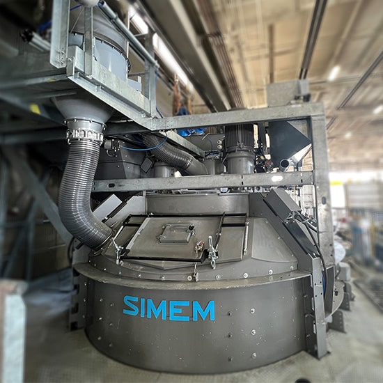
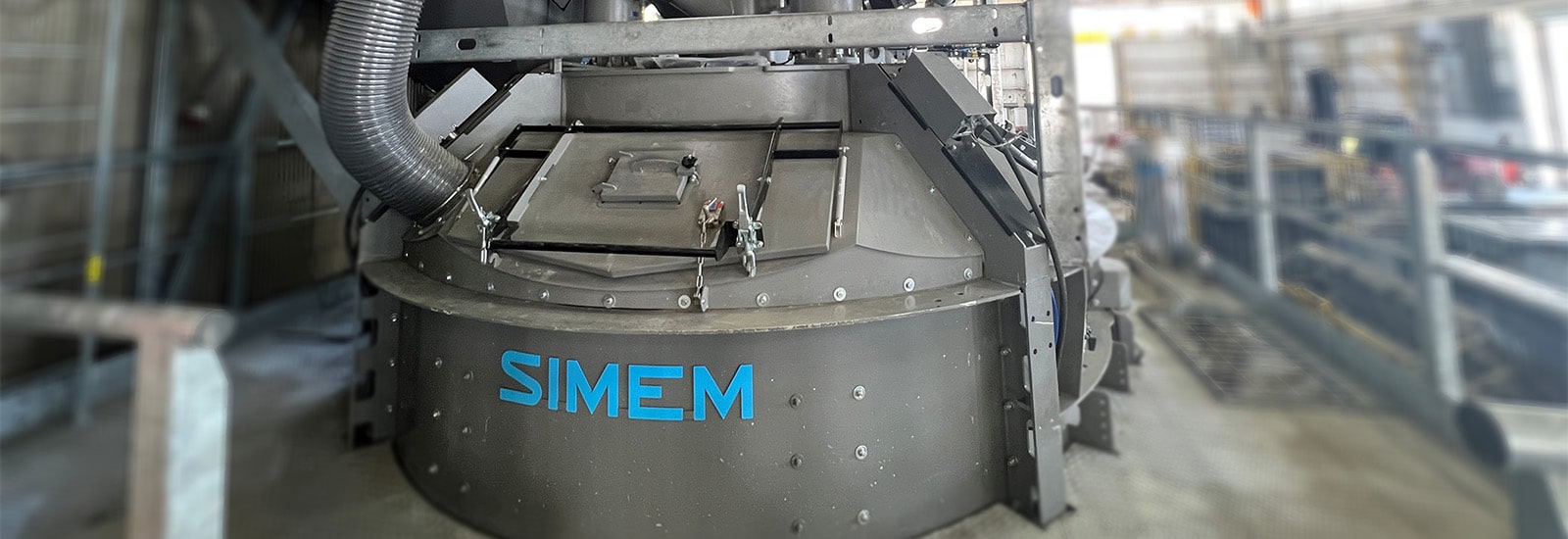
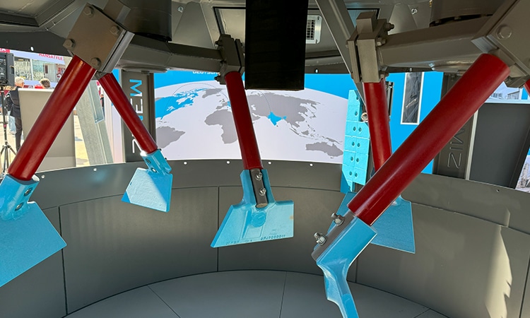
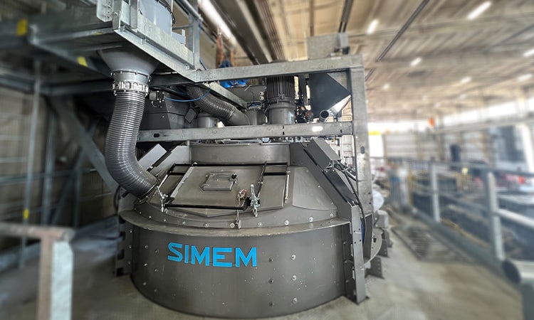
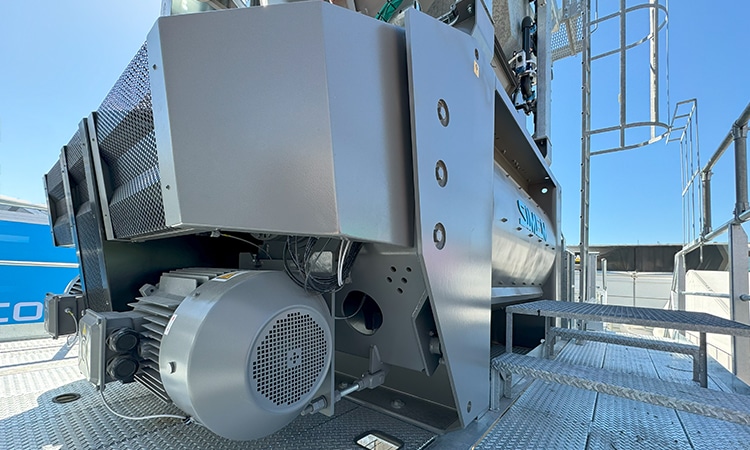
Twin Shaft Mixers

Renowned for durability, longevity, and predictable performance, MSO Mixers are available to serve a range of concrete outputs from 1.5 yd3 to 12 yd3, all suitable for the production of standard wet concrete, SCC, RCC, and MASS (very large aggregate concrete). A combination of heady-duty design, maintenance ease, and wear part hardness lends the lowest maintenance cost per yd3.
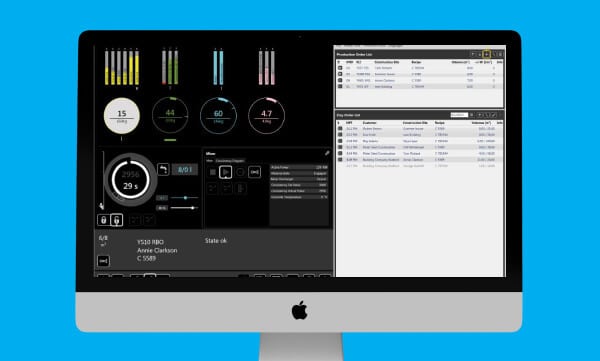
Simem@Tic3.0

Simem@tic 3.0 is the automation program with a friendly interface which displays all essential plant operation information. A full process sequence view (loading, weighing, recipe, discharge, washing, production listing, pending orders) with self-adjusting software for a predictable and repeatable outcome. All production data is recorded and stored in SQL database format providing detailed record of concrete production.

Specifications

Model2500400050007000
Mixer – Twin ShaftMSO 2501MSO 4001MSO 5001MSO 7001
Concrete Output m3(cy)/hr70 (90)100 (130)130 (170)180 (235)

Xentrix

With features like central cement and water inlets, as well as a modular design, Xentrix has taken the planetary mixer to a new level – making it suitable for the production of precision concrete for tunneling and mining applications.

Features

Exclusive Design

The design of Simem Xentrix planetary mixers has an off-center positioning of the main mixing arms for central charging of cement, water, and additives which makes it a leader in its class with the best possible mixing action. The mixing is highly efficient due to the integrated action of central satellites (1 or 2 depending on the model) in planetary rotation for a centrifugal effect. An innovative system which distributes water in a 360° umbrella pattern adds to mix efficiency and consistency.

Mixing Paddles

Mixing paddles are made of cast iron or combination of a cast iron core lined with wear resistant rubber material, which optimizes the material flow.

Mixing Tank

Designed for optimal wear resistance, the tank is lined with interchangeable wear liners. A floor with a flexible configuration makes it possible to re-position the bolted liners, allowing for future discharge door addition. Oversized inspection doors ease access for maintenance, while inspection doors remain in tack.

SuperWash and MixerMind Electronic Check

SuperWash, automatic washing unit, is available as option, with electric pumps, 16 gal water flow, 2900 psi water pressure, and touch screen control.

Specifications

ModelX2001X2501X3002X4002X4502
Dry filling capacity l/cy1,875/2.52,250/3.03,000/3.93,750/4.94,500/5.9
Output capacity l/cy1,250/1.61,500/2.02,000/2.62,500/3.33,000/4.0
Main mixing stars22222
Paddles per main mixing star33333
Secondary mixing stars22
Paddles per secondary mixing star22
Side scrapers22222
Mixer drive motors kW/hp2×22/302×30/402×44/603×30/403×37/50

VortiMix

The high-shear colloidal mill is recognized as the most efficient method of mixing bentonite, cement, fly ash, etc., with water. The intense mixing action results in homogeneous and stable mixes. Colloidally-mixed cementitious products are found to better resist bleed and provide higher compressive strengths than comparable materials prepared in lower energy, paddle-type mixers.

Features

High-Shear Colloidal Mixers

VortiMix is Simem’s new line of advanced high-shear colloidal mixers. The VortiMix can rapidly mix cementitious grouts as low as 0.5:1 water:cement ratio (by weight). When combined with an optional paddle assist, VortiMix can handle grouts as low as 0.45:1 w:c ratio, making the mixer ideal for lightweight cellular concrete applications. Hydrated bentonite can also be rapidly prepared in the VortiMix yielding improved gel strengths and reduced hydration times.

Specifications

ModelVM500VM1000VM2000
Batch size l (gal)500 (132)1000 (264)2000 (528)
Max. capacity m³(cy)/hr7.5 m3/h (9.8 yd3/h)15 m3/h (19.6 yd3/h)30 m3/h (39.2 yd3/h)
Colloidal MillsOne x 22 kW / 30 hpOne x 30 kW / 40 hpTwo x 30 kW / 40 hp

Performance Benefits of Colloidally Mixed Two-Component Grouts

Originally published in ITA – AITES WTC 2016

Philip Antunes, P.E., P.Eng. – Team Mixing Technologies Inc.
A.E. (Tony) Reschke, M.Sc., P.Eng. – Team Mixing Technologies Inc.

INTRODUCTION

Tunnel Boring Machine (TBM) operations require the injection of material into the annular tail voids as the machine advances ahead of the segmental concrete lining. This annular gap is created because the cutting diameter of the TBM has to be larger than the outer diameter of the concrete segments of the tunnel lining.

Fundamentally, the two basic types of annular grout are thick, concrete like mortars and thin, mobile, two-component grouts. While some European countries seem to still favor the concrete like mortars, from a global perspective it is now the two-component type grouts that dominate the industry.

Two-component type grouts are comprised of an “A” component grout (typically cement, flyash, bentonite and a retarder/stabilizer) and a “B” component accelerator (sodium silicate or water glass as it is sometimes known). They are thus sometimes referred to as A/B type or bi-component grouts and were pioneered by the Japanese over 30 years ago. They offer a host of operational benefits over thick mortars, such as reduced settlement (Feddema et. al., 2001), effective penetration of the void space, with less energy, and reduced strain on the segmented linings (Robinson et. al., 2007). Two-component grouts are highly mobile and can be pumped many kilometers. The use of a retarder/stabilizer can also extend the shelf life of the “A” component grout for several days while the early strength of the accelerated grout stabilizes the ground and supports the segmental liner almost immediately.

The batch plants that prepare the two-component grouts use one of two possible mixing methods for preparing the “A” component grout. The simplest plants use paddle type mixers and numerous tunnels worldwide have been successfully grouted using this technology. However, a superior type of mixer is available, namely the high shear colloidal mixer.

Keller Colcrete successfully pioneered the development of the colloidal mixer back in 1937 and for over 75 years colloidal mixers have been internationally recognised as the most efficient method of mixing cement based grouts (Houlsby, 1990). These mixers are used in grout preparation for radioactive waste encapsulation, hydro dam grout curtains, soilcrete jet grouting, soil nailing, and numerous other geotechnical applications. In tunnelling, these mixers are also used for ground treatment, compensation grouting and for the preparation of bentonite lubrication for pipejacking. It has been only within the last decade however that these high-shear colloidal mixers have been adapted for use in the preparation of two-component grouts.

PRINCIPLES OF HIGH-SHEAR COLLOIDAL MIXING

Colloidal mixer design

While several brands of colloidal mixers are now available, the Colcrete type mixer design will be discussed below. Readers are referred to Houlsby (1990) for a more detailed design comparison of other commercially available colloidal and paddle type mixers.

Colloidal mill

The key element of the colloidal mixer is the colloidal mill (see Figure 1). The mill is comprised of a high speed rotor (or discar) operating at 2100 rpm coupled with a close fitting chamber housing. The discar is free to float horizontally on its mounting shaft with the internal fluid pressures centralising it in the housing. The clearance between the discar and the walls of the housing is approximately 3 mm. It is here that a violent turbulence and high shearing action is created which is capable of breaking down clusters of dry cement particles (agglomerates).

Figure 1: Components of a high shear colloidal mixer (after Reschke, 1998).

The colloidal mill also acts as a centrifugal pump. In a grout plant the colloidal mixer can thus directly discharge the mixed slurry into an agitation tank. The colloidal mill is capable of generating a maximum discharge pressure of 200 kPa. Depending on the batch size of the mixer, there may be up to 4 of these mills operating in unison each with a throughput of up to 750 l/min (200 USgpm).

It is possible to increase the mills efficiency as a pump (thus giving it a higher pressure capacity) but this would reduce its efficiency as a mixer. In fact, it is this lower pump efficiency that translates into more effective work being done on the material being mixed. There is simply more energy input into the mixing with the colloidal mixer. To illustrate this further, a 2000 litre colloidal mixer would have 4 x 22 kW motors (88 kW total) versus a 2000 litre paddle mixer which may have a single 15 kW mixing motor. More energy equates to better mixing.

The strong vortex action inside the tank rapidly assimilates the mix ingredients (cement, flyash, bentonite and admixtures) in as little as 2 minutes. The resultant slurry exhibits colloidal properties, i.e. the cement particles remain in suspension with minimal settling or bleed.

Mixing tank

The mixing tank, besides holding all the ingredients, also acts as a centrifugal separator. The centrifugal action of the circulating material spins the unmixed, thicker grout towards the outside of the tank whereas the lighter portions of the mix (the water and partly mixed grout) move inwards towards the throat of the tank and into the colloidal mill. Once through the mixer this lighter material is discharged tangentially into the outer part of the vortex, thus blending with the thicker, unmixed grout. Multiple passes through the rotor produce thicker and thicker grout until the entire mix becomes uniform and the centrifugal action can no longer separate differing densities. At this point the surface of the vortex has a smooth, uniform appearance.

The vortex action created inside the tank also helps to rapidly assimilate any admixtures into the mixer when first added. Depending on the size of the mixer the entire mixing process can take as little as 15 seconds.

Colloidal Suspensions

While the term ‘colloidal’ is often applied to high-shear mixers and the slurries they produce, strictly speaking, the term is incorrectly applied. ‘Semi-colloidal’ or ‘near-colloidal’ are more accurate descriptions. A colloid is defined as a solid, liquid, or gaseous substance made up of very small, insoluble, nondiffusible particles (as large molecules or masses of smaller molecules) that remain in suspension indefinitely in a surrounding solid, liquid, or gaseous medium of different matter. With cement based slurries, it is possible to filter out the solids (though perhaps not all if the cement is microfine) and individual grains can readily be seen. Particles will settle out leading to grout bleed. Cement slurries are thus not true colloidal suspensions.

The effect of the colloidal mixer, however, is to aggressively shear and break down individual cement grains and to make cement hydrates form of colloidal size such that the slurry exhibits colloidal properties, or in other words, forms a stable suspension.

Properties of high quality grouts and slurries

A high quality grout or slurry is regarded as having the following properties (Houlsby, 1990).

  • Every particle of cement in the mix is thoroughly wetted. Individual grains are separate from each other without flocs or clumps.
  • Each cement grain is surrounded by a film of water which chemically activates the particle, giving the full hydration necessary for strength and durability.
  • The cement is thoroughly mixed with any other constituents of the mix or admixtures.
  • The grout or slurry is uniform throughout.
  • The mix exhibits some colloidal characteristics because of the maximum gel formation of the cement.

All of these properties can be attained with the use of high shear, high speed colloidal mixers. Kravetz (1959) explains that the high-speed shearing action combined with the centrifugal action of colloidal mixers thoroughly breaks up cement clumps and separates air bubbles, both of which slow the wetting process of cement grains. As a result, each grain is rapidly and thoroughly wetted and put into suspension. The mixing action also continually breaks away the hydrates that form on the surface of wetted cement grains exposing new areas to water. The hydrate elements that form are of colloidal size and as the amount of these elements increases the mixture becomes more colloidal in character.

Mayer (1959) measured the effect of high-shear colloidal mixing on cement grain size, particularly grains under 20 μm in size. The percentage of grains 5 μm in size was shown to be twice as large after high-speed mixing than with ordinary mixers, which accounted for the fact that the suspensions obtained were much more stable.

Practical benefits of colloidally mixed products

The practical benefits of colloidally mixed grouts and/or slurries include:

  • The grout or slurry mix is nearly immiscible in water. This allows the mix to resist washout or contamination with groundwater.
  • The mix is stable and fluid enough to allow it to be pumped considerable distances.
  • The slurry permeates uniformly into voids.
  • Segregation of sand, if incorporated in the mix, is virtually eliminated.
  • The grout or slurry has less settlement (bleed) of the cement when stationary.
  • Higher compressive strengths.

Colloidal mixers are clearly superior to paddle type mixers in the preparation of neat cement based slurries (Reschke, 1998) used in mining applications. As per Figure 2, higher strengths can be attained by virtue of the quality of the mixing of the cement and the water.

Figure 2: The 28-day strength of colloidal and paddle mixed grout (after Reschke, 1998).

EFFECTS OF MIXING INTENSITY ON TWO COMPONENT GROUTS

Test Methods

To illustrate the benefits of using colloidal mixers in the preparation of two-component grouts comparative tests were conducted on a typical grout recipe (see Table 1) using a proprietary Team Mixing lab scale colloidal mixer, a model 130 Jiffler mixer in a ½” drill operating at 500 rpm, and a bench top Hobart HL120 mixer with paddles.

Table 1: Typical Two-Component Grout Mix Design

There are several key properties of two-component annular grouts that need to be considered in order for the stabilized and then accelerated grout to be effective. These include:

  • Viscosity – critical to pumping requirements and the flow of grout in the annular gap.
  • Bleed – critical to stability of grout in the pipeline.
  • Gel time – need rapid gelling to lock segments in place
  • Compressive strength – to support weigh of backup gantry bogey wheels.

All properties were tested in general accordance with ASTM standard procedures. Flowability was measured using a flow cone as per ASTM C939 specifications. Newtonian viscosity was measured directly from a Fann Model 35 Viscometer. Bleed was measured in graduated cylinders as per ASTM C940. Gel time was measured by mixing the grout and accelerator in a bucket and pouring the contents from one bucket to another until the grout will not flow any more. For early age compressive strength (<24 hrs or 1.5MPa) samples were tested using a constant strain rate loading frame as per ASTM D2166. For higher strength testing (>24 hr or 1.5MPa) then a constant load rate testing frame was used following C109 procedures. Readers are referred to Antunes (2012), for specific details on test methods and recommended deviations from ASTM standards to suit the particular properties of two-component grouts.

Test Results

Table 2 summarizes the average test results and, based on the authors experience, compares these to the desired range of properties required for the successful use of two-component grouts in tunneling.

Table 2: Two-Component Grout Properties with Various Mixers

Viscosity

If the two-component grout is to be pumped from the surface batch plant to the TBM then flowability and viscosity are particularly important in determining pipeline specifications and surface pump pressures. A lower viscosity is preferred as it results in lower pipeline and pump pressures as well as lower power consumption. This becomes increasingly important the longer the conveyance pipeline gets. Test results indicate that the high shearing action of the colloidal and Jiffler mixers yield similar results. Interestingly the low intensity Hobart mixer actually yields lower viscosities. However, this is a result of the poor mixing action being unable to adequately break down the cement agglomerates and to disperse the bentonite particles (which causes gelling in the grout). Clumps of bentonite were visible in the Hobart mixed grout whereas the colloidal and Jiffler mixed grouts were homogenous in appearance.

Bleed

As with the discussion above on viscosities, grout bleed is an important consideration when pumping the grout to the TBM. Bleed within the grout results in settling of the cement particles along the invert of the pipeline. Severe bleed eventually leads to a constriction in the pipeline which requires higher and higher pump pressures to overcome. Regular cleaning of the lines with “pigs” can alleviate this problem to a point, particularly in lines less than 3,000 m. However, it is much more desirable to minimize the bleed from the onset. As contractors give serious consideration to pumping up to 9,000 m without any booster pumps in the tunnel, bleed becomes an absolutely critical parameter. The paddle type Hobart mixer simply does not provide adequate shearing action to disperse the bentonite. Consequently, the levels of bleed are unacceptable and not conducive to successful long distance pumping.

Gel Time

Generally speaking, longer gel times are more desirable as the single most common issue with the use of two-component grouts is blockages within the injection lines and ports after the accelerator is introduced. Longer gel times give adequate time for the accelerated grout to move from the injection lines out into the annular gap. Based on the test results the higher shear mixers give slightly longer gel times and are thus preferred.

Unconfined Compressive Strength (UCS)

The most common performance specification for the grout, given by designers and contractors, is an early compressive strength requirement. Early strengths are needed to ensure the segments do not sink within the annulus once internally loaded by the TBM backup gantry and to ensure adequate load transfer between the segmental lining and the soil. It is thus one of the most important performance parameters to consider.

All mixers tested gave adequate results for the 1 hr compressive strength. The Hobart mixer actually showed marginally better results but again this can be attributed to the poor dispersion of bentonite as bentonite is known to reduce the strengths of cement based grouts. The highest 28 day strengths were achieved with the colloidal mixer however the Jiffler mixer closely approximates the mixing quality of the colloidal mixer and appears to be a suitable lad mixer for simulating a high shear colloidal mixer.

Field Results

Figure 3 shows the field results achieved for grout strengths on the Airport Link Project in Brisbane (Reschke et al., 2011). The average results are shown (red dots) and compared to the initial lab results (open circles) which were conducted with a Hobart mixer for the same recipe. Once again we see significantly higher strengths attained from the use of a high shear colloidal mixer versus a low intensity paddle type mixer. For this particular grout recipe, the colloidally mixed grout had almost double the strength of the paddle mixed lab result used to determine the recipe for the project. The field results were so impressive that eventually the cement content in the grout was reduced by 7%. This resulted in a substantial cost savings to the contractor. Even with this cement reduction the strength performance still exceeded the minimum contractual requirement. Further reductions in cement content were therefore possible. The contractor however did not want to add any risk to the grouting program as this was the largest diameter TBM ever used in Australia at that time, and consequently, further optimization of the grout recipe was not pursued.

Similar strength gains were also encountered on the recently completed Istanbul Strait Road Tube Crossing Project under the Bosphorus. The two-component grout recipe was predetermined by lab testing with a paddle type mixer. In the field however, cement usage was actually reduced by 10% through the use of a colloidal mixer based batch plant (Gönenς, 2015).

Figure 3: Effect of Mixer Selection on Two-Component Grout Strengths (after Reschke, 2011).

Also shown in Figure 3 are field results for a paddle mixer based batch plant used on the Sydney Desalination Project (the circles with the cross). The grout mix recipe used here was virtually identical to the original Airport Link Project recipe. It can be seen that the grout strengths achieved in the field using a batch plant with a paddle mixer coincide extremely well with the lab test results using a paddle type Hobart mixer. This implies that the Hobart mixer is a useful lab tool that gives realistic results for field scale paddle mixer type style batching plants.

CONCLUSIONS

Both lab and field results have demonstrated the superior mixing capabilities of a high shear colloidal mixer versus a paddle type mixer. Higher strengths and lower bleeds result from the more energy intensive mixing action. As a result, the cement content in the “A” component grout can be reduced by up to 10% resulting in significant cost savings for the contractor. Lower bleed is also a critically important parameter to take into consideration if long (>3,000 m) pump distances are considered for a project.

Recent testing has also confirmed that the Hobart type paddle mixers are accurate for predicting field results of paddle mixer based grout batching plants. Conversely, the Jiffler style of lab mixer is better suited to predict the field properties of a colloidal mixer based grout plant.

REFERENCES

Antunes, P.F. 2012. Early Age Testing Procedure of Two-Component Annulus Grouts. In North American Tunnelling Convention 2012 Proceedings. Englewood, CO: Society for Mining, Metallurgy and Explorations, Inc. pp. 14-22.

Houlsby, A.C. 1990. Construction and Design of Cement Grouting – A Guide to Grouting in Rock Foundations. New York, NY: John Wiley & Sons. pp. 10-28.

Feddema, A., Moller, M., van der Zon, W.H. and Hasimoto, T. 2001. ETAC Two-Component Grout Field Test at Botlek Rail Tunnel. In Modern Tunnelling Science and Technology. Kyoto, Japan.
Gönenς, Ö. 2015. Personal communication, April.
Kravetz, G.A. 1959. Cement and Clay Grouting of Foundations: The Use of Clay in Pressure Grouting. ASCE Journal of Soil Mechanics and Foundation Division. New York, NY: American Society of Civil Engineers. pp. 109-114.
Mayer, A, 1959. Cement and clay grouting of foundations: French grouting practice, ASCE Journal of Soil Mechanics and Foundation Division. New York, NY: American Society of Civil Engineers. pp. 41.
Reschke, A.E. 1998. The Development of Colloidal Mixer Based CRF Systems. In MINEFILL 98, Edited by Dr. M. Bloss. Carlton, Australia: Australian Institute of Mining and Metallurgy. pp. 65-70.
Reschke, A.E. and Noppenberger, C. 2011. Brisbane Airport Link Earth Pressure Balance Machine Two Component Tailskin Grouting – A New Australian Record. In 14th Australasian Tunnelling Conference 2011. Carlton, Australia. Australian Institute of Mining and Metallurgy. pp. 609-617.
Robinson, B. and Bragard, C. 2007. Los Angeles Metro Gold Line Eastside Extension – Tunnel Construction Case History. In Proceedings Rapid Excavation and Tunneling Conference, Edited by M Traylor and J Townsend. Littleton, CO: Society for Mining, Metallurgy and Exploration. pp. 472-494.

Download PDF

Performance Analysis of Fly Ash in Two-Component Grouts

Originally published in Rapid Excavation and Tunneling Conference Proceedings

Phillip Antunes – Team Mixing Technologies Inc.

ABSTRACT

While fly ash is often used as a partial substitute for cement in civil construction, its usage in two-component grouts for TBM annulus grouting is varied. Opinions on the benefits of fly ash vary from person to person and project to project as do the economics. While most tunnelling projects use fly ash in two-component grouts a significant number of projects do not. The purpose of this paper is to quantify the performance of fly ash in two-component grouts by testing the compressive strength, bleed, gel time, and viscosity and also comparing these same parameters with fly ash from different geographic sources.

INTRODUCTION

The use of natural pozzolans predates modern Portland cement by about 2,000 years. Numerous structures built using volcanic ash—a pozzolan—mixed with burned lime are still standing today. In fact, the term pozzolan is derived from the volcanic ash mined at Pozzuloli, a village near Naples, Italy, following the 79 ad eruption of Mount Vesuvius (Derucher et al., 1994). It is not surprising then to see pozzolans, though predominately now synthetic, still in high demand today.

A pozzolan, by definition, is a “siliceous or aluminosiliceous material which in itself possesses little or no cementitious value but will, in finely divided form and in the pres- ence of moisture, chemically react with calcium hydroxide at ordinary temperatures to form compounds possessing cementitious properties” (Derucher et al., 1994). In short, pozzolans are powders that will harden when combined with lime and water at normal temperatures.

Fly ash, the most widely used pozzolan in concrete, is a by-product from the combustion of pulverized coal in electric power generating plants. Upon ignition, most of the volatile matter and carbon in the coal are burned off. However, the coal’s mineral impurities either settle to the furnace bottom as bottom ash or fuse in suspension and are carried away by the exhaust gases to cool and solidify into spherical glassy particles called fly ash (Komatka et al., 1994).

UNDERSTANDING FLY ASH

Types of Fly Ash

As is the case with any raw material, varying the geographic source of fly ash may affect the properties and performance. There are two primary classes of fly ash used with cement: Class F and Class C. Class F fly ash is produced from burning older anthracite or bituminous coals with a low calcium content, CaO (Calcium hydroxide or quicklime, as it is commonly known) < 15%, and has no cementitious properties on its own. Class C fly ash is produced from burning younger lignite or sub-bituminous coals and are further sub-classed as intermediate calcium content (CI) with 15% < CaO < 20% and high calcium content (CH) with CaO > 20%. Importantly, as a result of the high CaO content, Class C fly ash will hydrate and harden on its own in the absence of a cementing agent or activator (Komatka et al., 1994).

How Fly Ash Works

When Portland cement and water are combined, compounds of calcium silicates (CS) and water react to form a calcium silicate hydrate (CSH) gel and calcium hydroxide (CH). The CSH is the binder while CH is not. By adding fly ash which contains reactive silica, however, the CH will react to form more CSH. Fly ash also acts as a microfiller between cement particles reducing permeability and bleed water (King 2005).

Fly Ash Advantages

While fly ash was once only a waste product, its use has steadily increased over the last 40 years. That said, still only 43.7% of fly ash was used in 2013 in the U.S. and the rest—approximately 30 million tons—was landfilled as waste (www.acaa-usa.org/Publications/Production-Use-Reports. 01/14). When it is utilized, however, it often realises a further environmental benefit by substantially reducing the CO2 emissions of concrete. Fly ash can also result in regulatory body issued incentives to related projects and facilities. This, coupled with the fact that it is cheaper at the production source than cement, often results in both environmental and economic benefits.

The use of fly ash in concrete also has several known physical advantages includ- ing the reduction of water demand, bleed water, heat of hydration, and permeability while also extending set times, increasing pumpability and, generally, the long term strength (King 2005).

As many of these benefits are also desirable in two-component annulus grouts, fly ash use in tunnelling is common. (Two-component grouts are also known as “bi- component” or “A/B type” grouts.) Annulus grouts, however, differ substantially from concrete in that they contain no aggregates and the water to cement ratio varies roughly between 2.0 and 3.0 versus 0.4 to 0.6 in concrete. The questions thus arises, do two- component annulus grouts see the same benefits from fly ash that concrete does?

Fly Ash Disadvantages

Apart from the performance of the grout itself, the logistics of obtaining and utilizing  fly ash also need to be considered. Tunnelling projects are generally short term projects of intense activity executed within the tight physical boundaries of urban space. Consequently, these sites are often required to minimize and prioritize site activity. Using fly ash, however, requires a separate storage silo and conveyance system which may occupy valuable space and the benefit-cost ratio may be low for the additional equipment in a project with a timeline that is measured in months. Fly ash deliveries also require coordination with other site traffic and an awareness of the different raw materials. It has been the author’s experience that many sites using both fly ash and cement will, at some time during the project, place fly ash in the cement silo or vice versa causing downtime and economic loss.

The material savings from using fly ash may be muted by the added cost of transportation. As fly ash is produced by coal fired plants it will not be locally available if power generation is done by other methods, as is the case in the Pacific Northwest. Accordingly, as a result of both the transportation cost and increased demand in the concrete industry, the author has seen the delivered cost of fly ash within 10% of the cost of cement in several regions.

TESTING

Testing Methods

The laboratory procedures used for testing two-component grouts were previously developed by the author (Antunes 2012). It is important to note that these procedures include provisions for sample testing at various grout ages to capture any performance changes between the time the grout is first mixed and when it is ultimately injected into the annulus. Accordingly, the samples were tested at 1, 4, 24 and 48 hours as these times reflect the range of times that the grout is typically used within tunnelling projects.

It is also important to note that a colloidal mixer was used to mix the grout used for testing. It has been shown that colloidally mixed grouts achieve substantially higher compressive strengths and lower bleed water than grout mixed in traditional paddle type mixers (Reschke and Noppenberger 2011; Reschke 1998).

Ingredient Sources

The geographical source and type of fly ash are expected to affect the grout testing results. As transportation costs can be almost as much as the cost of the raw product, many project sites do not have the luxury of economically obtaining fly ash from different sources. The intent of this research is also to determine the impact that varying the source of fly ash can have on the annulus grout performance. As such, fly ash for the tests was sourced as follows:

  • Control—Class F
  • Northwest—Class F
  • Southwest—Class F
  • Northeast—Class C
  • Southeast—Class C

All other ingredients were held constant:

  • Cement—Type 1/GU
  • Bentonite—Wyoming source
  • Retarder— Pozzolith 100XR (BASF)
  • Accelerator—Sodium Silicate N38

Mix Design

The mix design shown in Table 1 Test Results was used for all tests. It is based on a typical two-component grout with a 1 hour strength of 0.1 MPa and a 28 day strength of 3.5 MPa while being stable for at least 48 hours. (This mix design should not be used without testing with locally sourced materials as properties could vary substantially.) The intention was to provide a simple control mix to establish baseline parameters from which the effects of varying fly ash content could be studied. Five different fly ash/ cement ratios were tested for each of the five fly ashes sourced: 0:1 (0% fly ash), 1:3 (25% fly ash), 1:1 (50% fly ash), 3:1 (75% fly ash) and 1:0 (100% fly ash). Note that the 75% and 100% fly ash ratios are not typically used in practice but were included to capture the data extremes.

Table 1. Two‑component grout mix design
Figure 1. A‑component apparent viscosity with age

TEST RESULTS

Two-component annular grouts are typically mixed on surface and then pumped to the TBM via a steel pipe. Several mix properties need to be considered to allow the stabilized and then accelerated grout to be effective. These include:

  • Viscosity
  • Bleed
  • Gel Time
  • Compressive Strength (Antunes 2012).

Though the testing produced over 25 charts and numerous tables of data, the trends were remarkably similar between each fly ash tested. As such, the data was averaged to produce graphs that concisely indicate the trends observed.

Viscosity

The viscosity of the A-component is particularly important in determining pipeline specifications and surface pump pressures. A lower viscosity is preferred as it results in lower pump and pipeline pressures as well as lower power consumption.

Figure 1 shows the viscosity of the A-component grout with age and with varying fly ash contents. An important observation is that increasing the amount of fly ash in the mix lowered the mix viscosity. As length and diameter of tunnels are increasing— requiring higher grout volumes and pumping pressures—lower mix viscosities are a direct benefit to the grout conveyance system. Although increasing the retarder/stabilizer dose also reduces the viscosity, it also adds cost to the mix.

Table 2. Effects of aging grout on pumping pressures
Figure 2. Gel time

Of additional note is that all mixes had a relatively low viscosity when first mixed. However, as the stabilized grout aged, the viscosity increased in each case except for the 1:0 ratio which consisted of fly ash only (no cement). The practical implications of the effects of aging grout can be illustrated using the 1:3 ratio mix and the following assumptions:

  • Pumping 15 m3/hr of grout
  • 3″ Sch 40 steel pipeline
  • 3 km long with no elevation change
  • Grout specific gravity 1.23

Table 2 shows the theoretical pumping pressures in relation to the age of the grout.   It is clear that as the A-component grout ages the pump pressure requirements climb substantially. This is an important factor to consider when selecting equipment for the project. It is also interesting to note that there is a drop in pressure between the 0 and 4 hour viscosities. This is due to the transition between laminar and turbulent flows in the pipeline. This transition will occur with any fluid and is a function of the pipe diameter, fluid velocity, and viscosity.

Gel Time

When the A and B components are combined, a gel starts to form in a short period of time (<40 s). This accelerated grout needs to remain fluid long enough to uniformly fill the annular space behind the tunnel segments without leaving voids. Conversely, the grout must also gel quickly enough to lock the segments in place and to resist being washed out by groundwater.

Figure 2 shows the effect of aging on grout gel time as well as the effect of fly ash content on gel time. There is a consistent trend that gel time increases with increased fly ash content and with the age of the grout.

Figure 3. Bleed water

Based on the author’s experience, a gel time between 15 and 40 seconds is considered favourable, though this varies primarily on how many injection ports are being used on the TBM and the corresponding time required to fill the void. The results show that fly ash ratios up to 1:1 increased the gel time favourably. Gel time can also be affected by adjusting the B-component (also known as accelerator) dose. Contrary to general thought, however, increasing the B-component dose will actually increase your gel time though when it does gel, it will also result in higher early compressive strengths.

Bleed

The conveyance line delivering the A-component grout from the slurry plant to the TBM forms the critical link tying together grout production and TBM advance. Recognizing and minimizing bleed is necessary to reduce the risk of pipeline sedimentation and/or blockage. If the grout bleeds significantly, heavier particulates may begin to accumulate in the invert of the grout line and eventually reduce the cross sectional area of the pipe. This will lead to higher pumping and line pressures, lower flow rates and may ultimately completely occlude the pipe. As the high water/cement ratio of two-component grouts causes them to bleed excessively and rapidly, controlling bleed is critical and bentonite is the primary ingredient to accomplish this.

The effects of fly ash on bleed are shown in Figure 3. The 1:3 fly ash/cement ratio grout shows a substantial reduction in bleed as compared to the grout prepared with no fly ash. However, the addition of still more fly ash does little to further reduce the bleed. As bentonite dosages are generally low, the impact to the mix cost is relatively small. Even so, the use of fly ash can still benefit the mix by reducing bleed.

Strength

The most common performance specification for the grout, given by designers and contractors, is an early compressive strength requirement. Early strengths are needed to ensure the segments do not sink within the annulus once internally loaded by the TBM backup gantry and to ensure adequate load transfer between the segmental lining and the soil.

Figure 4. Compressive strength
Table 3. Compressive strengths

Figure 4 shows the effects of fly ash on the compressive strength of the accelerated grout and reveals a clear trend: as fly ash is increased, compressive strength decreases.

Table 3 contains the underlying data for Figure 4 to better quantify the effect that the fly ash ratio has on the compressive strength.

The compressive strength is clearly the property that suffers with the addition of fly ash. The early (i.e., <4 hr) strengths can be compensated for by increased accelerator to some degree. However, as the B-component is one of the most costly components of the mix, this option should be considered sparingly. If a higher long term strength  is also needed, lowering the water/cement ratio is considered to be the best option. Unfortunately, reducing the water/cement ratio will increase viscosity and bleed and decrease the gel time. Testing is thus needed to optimize the project specific properties while reducing material costs.

Of additional interest is the effect that the age of the grout has on the compressive strength. After the A-component grout is mixed on surface, it can take anywhere from an hour to a few days before the grout is combined with the B-component. Figure 5 shows that as this wait time increases in grout containing fly ash, the 1 hour compressive strength actually declines whereas the opposite was true in grout with just cement. There were slight variances to this trend at the 1 and 28 day strengths but the overall trend indicates that this should be considered in mix design development.

CONCLUSIONS

The test results for two-component grouts utilizing fly ash from different geographic regions showed similar trends in data for each fly ash/cement ratio considered.

Figure 5. Grout age effect on 1‑hour compressive strength

Viscosity and bleed saw pronounced decreases with fly ash addition which has positive implications to the design of the conveyance system. Gel time was increased which is favourable for the injection process. Compressive strength, however, decreased with the addition of fly ash. It has been the author’s experience that the grout benefits gained when using fly ash generally diminish when having to compensate for the reduced compressive strength. The testing conducted for this research did not specifically look at optimizing the mix design for a given compressive strength. Doing this may be beneficial for reference purposes but, in practice, would change from job to job.

REFERENCES

2013 Coal Combustion Product (CCP) Production & Use Survey Report. American Coal Ash Association, 2013. Web. 11 Jan. 2014. www.acaa-usa.org/Publications/ Production-Use-Reports.
Antunes, P. 2012. Early Age Testing Procedure of Two-Component Annulus Grouts.  In North American Tunnelling Convention 2012 Proceedings, Indianapolis, IN, June 24–27. Englewood, CO: Society for Mining, Metallurgy and Explorations, Inc. (SME).
Derucher, K; Korfiatis, G; Ezeldin, A. 1994. Materials for Civil & Highway Engineers, 3rd ed. Englewood Cliffs, NJ: Prentice Hall.
King, B. 2005. Making better Concrete: Guidelines to Using Fly Ash for Higher-Quality, Eco-Friendly Structures. San Rafael, CA: Green Building Press.
Komatka, S; Kerhoff, B; Hooton,R. McGrath, R. 2010. Design and Control of Concrete Mixtures, 8th Canadian ed. Ottawa, ON: Cement Association of Canada.
Reschke, A. and Noppenberger, C. 2011. Brisbane Airport Link Earth Pressure Balance Machine Two Component Tailskin Grouting—A New Australian Record. In 14th Australasian Tunnelling Conference 2011, Auckland, New Zealand, March 8–10. Australasian Tunnelling Society.
Reschke, A. 1998. The Development of Colloidal Mixer Based CRF Systems. In Minefill ’98, Brisbane, Australia, April 14–16. Carlton, Victoria, Australia: The Australasian Institute of Mining and Metallurgy.

Download PDF

Testing Procedures for Two-Component Annulus Grouts

Originally published in North American Tunneling

Phil Antunes – Team Mixing Technologies, Abbotsford, British Columbia

ABSTRACT

Despite the recent rise in popularity of two-component grouts for annular space grouting, there is a lack of standards and procedures on how to test two-component grouts for the specifications required by tunnel engineers. This leaves open for interpretation appropriate testing procedures which presents a problem particularly in quantifying the early strengths frequently required by designers. A recent survey of several tunnelling contractors showed that each had developed and adopted procedures unique to their establishment. The objective of this paper is to propose a standard and procedure for determining the early strengths of two- component grouts and other general properties.

INTRODUCTION

In soft ground tunnelling operations, tail voids are created as the TBM advances ahead of the segmental lining. These tail voids result from the cutting diam- eter of the TBM being larger than the outer diameter of the concrete segments. In order to stabilize the segments and reduce ground settlement, this annular space needs to be filled as the TBM advances.

There are two basic types of annular grouts currently in use: thick mortar type grouts and highly mobile two-component grouts. Two-component grouts consist of an A and B component and are also referred to as Bi-Component or A/B Type grouts. The A-Component is a stabilized grout containing varied combinations of water, binders, bentonite (usually), and admixtures. The B-Component is a liquid accelerator that is added to the A-Component as it is being injected into the annulus.

As two-component type grouts have a number of advantages over mortar  type  grouts  (Feddema et al., 2001, Peila et al. 2011; and Pellegrini and Perruzza 2009), they continue to gain in popularity. Consequently, industry standards need to be established to properly evaluate and the performance of these grouts.

TESTING PARAMETERS

As the A-Component is typically pumped from the surface grout plant to the TBM, several mix proper- ties need to be considered to allow the stabilized and then accelerated grout to be effective. These include:

  • Flowability and viscosity
  • Bleed and segregation
  • Stabilization time
  • Gel Time
  • Compressive strengths

For the purpose of proposing a guideline for the development and testing of Two-Component mix designs, ASTM standards have been referenced for the following procedures. It should also be noted that any mix results given in this paper were done using a high shear colloidal mixer with raw materials avail- able locally to the author. Mix properties may vary substantially based on mix quality and ingredients (Reschke 2011). Table 1 shows the mix designs used for this paper.

Flowability and Viscosity

The flowability of the A-Component is important to predict pumping requirements and pipeline specifications. Higher flowability is advantageous as it implies lower pump and pipeline pressures as well as lower power consumption. Flowability is affected by:

  • Water to cement ratio (W:C)
  • Solids content and whether bentonite is used
  • Admixtures
  • The time since the retarder was initiated

Flowability is measured using a flow cone as per ASTM C939–10. However, two points in this standard must be noted:

  • Bullet 7.6 of C939 requires mixing per ASTM C938 with a specified grout mixer. In order to gauge material flow it is recommended that a mixer be used that will accurately replicate the mixer that will be used for the project. Tests have shown that a mix prepared in a high-shear colloidal mixer for 1 minute had a flowability of 10.5 seconds while the same mix prepared in a standard lab Hobart mixer for 3 minutes required 16.5 seconds.
  • Depending on the pot life required of the sta- bilized grout, flowability per ASTM C939 is repeated in intervals that will indicate the flu- idity of the grout as it ages.

Though flowability and viscosity are related, one cannot directly indicate the other. It is beneficial to parallel flowability readings with viscosity, using a viscometer, as these can be used to calculate pump requirements and head losses in the pipe network.

Bleed and Segregation

The conveyance line delivering the A-Component from the surface plant to the TBM is critical to the advance of the TBM. Grout bleed can lead to accumulations in the pipe invert that will reduce the cross sectional area of the pipe. This leads to higher pumping pressures, lower flow rates, and may ultimately completely occlude the pipe.

Testing for bleed also provides the opportunity to verify that no segregation internal to the grout is occurring. It has been noted that some anti-segregation admixtures at low water/cement ratios produced little bleed water, < 2%, but still segregated internally (Figure 1). It is beneficial to allow the sample to cure within the graduated cylinder for later inspection.

Stabilizer/Retarder

While chemically a stabilizer and a retarder react differently, the terminology is often used interchangeably. It is important to establish how long the A-Component will be held dormant before the injection with the B-Component. If more retarder is added than needed, it will increase the cost of the mix and require a larger dosage of accelerator to start the rapid set. The larger amount of accelerator also adds cost and may reduce the final compressive strength of the grout.

Figure 1

Though there are some modified tests to deter- mine the “pot life” of a mix, it is most practical to test the effect of the retarder with the flowability test per ASTM C939 previously discussed. The allowable threshold for the flow time and viscosity should be specified and the mix tested to meet these guidelines.

Gel Time

Soon after the A and B components are combined the grout ceases to be fluid. The time to form this initial set is commonly called the gel time. Gel time is an important consideration as the grout needs sufficient time to distribute throughout the annulus but then gel quickly to prevent the segments from floating. There are different ASTM test methods for setting time and early stiffening of grouts but nothing for the rapid set reaction of two-component grouts.

Figure 2

Compressive Strength

Designers and contractors typically specify the strength requirement for the grout. Strengths requirements often range between 0.1 to 0.3 MPa (14.5 to 43.5 psi) at 1 hour and 1 to 3 MPa (145 to 435 psi) in 28 days. The early strength is required to ensure the segments can support the loads imposed by the back- up gantry as well as to transfer the loads between the segments and the soil. The testing of the relatively low 1 hour strengths, however, has proven problematic as there are no directly applicable ASTM standards.

Contractors and suppliers have adapted or developed their own standards to verify grout strengths. The methods vary from penetration resistance (Figure 2), modified Vicat (Figure 3), shear strengths tests, and unconfined compressive tests (Figure 4). When different testing methods are used, different results will be obtained as shown in Table 2. Though penetrometer and Vicat tests do indicate early compressive strengths, they are, at best, an indirect measurement. It has long been standard in concrete and grout testing to test cylinders and cubes as unconfined specimens. Though this is con- servative as the in situ grout will be constrained triaxially, the unconfined compressive strength (UCS) test does provide direct results of the compressive strength. Also, for consistency and correlation of data throughout the test period, it is preferred that the early and later compressive strengths are tested in as similarly as possible. The UCS test, then, provides the most representative data for compressive strengths and the ASTM standards can be referenced from this perspective.

Figure 3
Figure 4
Table 2. Peak 1-hr compressive strength test comparison

Cubes vs. Cylinders

The standards specify testing for UCS using cylinders having a 2:1 aspect ratio or 2-in (50mm) cubes. It is impractical, however, to use cylinders for early age (<4 hour) and low strength testing as it is difficult to extract the relatively fragile specimens from cylindrical moulds without damaging them. Also, cylinders often require capping to conform to perpendicularity requirements of ASTM C617-10. If cap- ping is necessary, the sample needs to be demoulded at least 10 minutes prior to testing to allow for the capping procedure. If the sample is already fragile at 1 hour, it is only more likely to be damaged if extracted earlier. As the strength gain during the initial hours is significant and notable within 5 minutes intervals as discussed later, the initial cure time is important. Furthermore, 2-in. cubes are commonly used to test grout compressive strengths in reference to ASTM C942 and C109 and, again, samples should be tested as consistently as possible between the specimen ages. For these reasons, ASTM standards to test early compressive strengths using cylinders are not ideal.

Contrastingly, the 2-in. cube moulds can be opened and the specimens removed with little interference to its contents. The mould is stripped from the specimen rather than the specimen from the mould and this can be done relatively quickly. 2-in. cubes can also be poured and screed with more accuracy than cylinders and do not require capping so testing can commence as soon as they are demoulded. Furthermore, they also provide dimensional consistency within the specimen test ages. The 2-in. mould is preferred for these reasons.

It has also been noted that, though ASTM D4832 is designed for controlled low strength material (CLSM) testing in cylinders, it is designed for specimens cured at and beyond 7 days. The difference between curing and cured—plastic and elastic—is important.

Plastic vs. Elastic

During initial hydration and strength gain, the two- component grout is still in a plastic, rather than elastic, state. In other words, loads imposed on an unconsolidated grout sample will cause permanent deformation. During compressive testing, the sample continues to balance loads imposed with axial consolidation, or strain. As the sample consolidates vertically, it expands laterally which increases its cross-sectional area. This area increase needs to be accounted for when calculating the stress.

Plastic testing is common in soils and ASTM D2166-06 outlines the procedure for unconsolidated testing using a rate of strain compressive testing machine. To be clear, cementitious samples are normally tested using a rate of load machine; the amount of load per unit time is monitored. For cured samples this is adequate as elastic failure occurs at or near peak loading. For plastic samples, the rate of strain machine measures the load per unit distance of vertical displacement. This allows for compensation of cross sectional area and these machines are designed and calibrated to test low strength materials.

Although early age grout is in transition from plastic to elastic, there is no clear point of transition. As a general guideline, however, samples may be tested using rate of strain when age <24 hr and/or the strength is <1.5MPa.

A-Component Stabilized Time

The age of the A-Component when the B-Component is added will have an effect on the early strengths  of the sample. If, for example, the A-Component    is designed to be stabilized for 8 hours and the B-Component is added to one sample at 30 minutes and a second sample at 7 hours since mixing, the 7 hour sample will see higher early strengths as the affect of the retarder would be waning. It should, then, be noted at what time the accelerator is added for testing.

Testing Time

At the early age strengths, the UCS between two specimens tested as little as 5 mins apart can be substantial as shown in Figure 5. Because of this, the rate of strain needs to be optimized to reduce the time for the test while still obtaining adequate resolution. For the 1 hour test, it has been found that starting testing on the first cube at 55 mins, the second at  60 mins and the third at 65 mins gives the best aver- age results for the 1 hour age. The compressive test itself should take 3 to 4 minutes and removing the sample from the testing machine, cleaning the debris and setting the next sample can take 1 to 2 minutes. As a general guideline, strain rates of 1mm/min for strengths of 0.075 to 0.15MPa and 0.75mm/min for strengths of 0.15 to 0.35MPa can be used.

Figure 5

TESTING PROCEDURES

The following is an outline of the testing procedure discussed above. As mixing procedures will vary depending on the equipment and materials, the proposal excludes mixing and sampling procedures and only provides details for testing the finished A-Component and accelerated grouts.

Flowability

ASTM C939 is used to test flowability of the A-Component with the following amendment and additions:

  • Mixing equipment and methods similar or the same as the final equipment should be used in place of C939.7.6.
  • The flowability should be checked at repeated intervals depending on the  characteristics  of the project. At a minimum, flow is taken immediately after mixing, at a mid-point and then at the end of required pot life of the grout.
  • If a viscometer is available, viscosities should be recorded at the same time the flows are.
  • Field testing indicated that flow times less than 17 secs and viscosities less than 125 cps are preferred. This can vary depending on tunnel requirements and pumping equipment used.

Bleed

ASTM C940 is used to measure bleed and if internal segregation is noted. Depending on the pot life required, the bleed is noted at intervals throughout this time, along with flow, and may extend past the three hour standard often referenced for this test. The bleed water should be decanted off as indicated in C940.9.5 of the standard and then the sample allowed to set in the cylinder. Once set, the cylinder can be turned over and the top hit on a firm surface to free sample—usually not as difficult to do as might be expected (Figure 6). Bleed should be less than 3% at 8 hours.

Figure 6

Gel Time

A simple procedure has been observed and tested to help quantify the gel time which is to pour the mixed grout back and forth between two containers until it will not pour any longer (Pellegrini, Perruzza 2009). The following is a variation of this procedure:

  1. Weigh 1 kg samples of A-Component in container suitable to mix the B-Component into.
  2. In a graduated cylinder, measure proportioned amount of accelerator for the 1 kg sample of A-Component.
  3. Have a second clean and empty container of equal size ready.
  4. While vigorously mixing with the A-Component, quickly add the B-Component in while starting the time and continue to mix for 5 seconds.
  5. Continue to mix the components by pouring from one container to the other until it will not flow any longer (Figure 7 and Figure 8).
  6. Record the time from when the accelerator was first added to when the grout would not flow as the gel time.

Figure 7
Figure 8
Figure 9
Figure 10

A and B Component Mixing

Depending  on  the  characteristics  of  the  specific retarder and accelerator,  this  procedure  may need some modification. However, for mixes similar to the tests used for this paper, the follow procedure provides consistent samples:

  1. Weigh 1 kg samples of A-Component in a container suitable to mix the B-Component into.
  2. In a graduated cylinder, measure proportioned amount of accelerator for the 1 kg sample of A-Component.
  3. Prepare a three-gang specimen mould per ASTM C109 5.3 and 9.1.
  4. While briskly hand mixing the sample of A-Component, quickly pour the B-component in and continue to mix for 5 seconds. The mix will be more fluid for approximately 5–15 seconds (Figure 9).
  5. Quickly pour the accelerated grout into each of the three cube moulds in a single pour; there will not be enough time to fill half way and tap surface per C942 10.3.2 (Figure 10 and Figure 11).
  6. The mix will generally set within 30 seconds and the excess grout must be cut off (ASTM C942 10.3.2).
  7. The mould can then be covered and stored per C942.

Compressive Strength

The compressive strength should be measured by two separate methods, depending on the age and curing properties.

Early Age

At < 24 hrs or 1.5MPa, the sample should be tested using rate of strain and referencing ASTM D2166 with the follow exclusions or amendments:

  1. D2166.5.2 is excluded as the cube samples can be easily demoulded (Figure 12).
  2. D2166.6 is excluded as the sample size will be 2-in. (50mm) cubes and the specimens created as described in “A and B Component Mixing” above.
  3. The procedure in D2166.7 needs to include an emphasis on time with early age samples. The rate of strain in 7.1 of ½ to 2% needs to also consider that the test must be completed within 4 minutes as discussed previously.
  4. D2166.9 should be modified to suit the annulus mix design and dry densities, saturation, etc., do not apply.
  5. D2166.10 was substituted with C109.13 and .14.

Figure 11
Figure 12

Later Age

For UCS testing > 24 hours or 1.5MPa C109.10.7–14 are used.

CONCLUSION

It has been shown that different procedures used to commonly test the early compressive strengths of two-component grouts can have a substantial impact on the results. This paper has described that for strengths less than 1.5 MPa and times less than 24 hours, a rate of strain unconfined compressive testing method should be used to accurately predict the compressive strengths of two-component grouts. Furthermore, procedures quantifying the flowability, bleed and gel time have been proposed based on applicable and, where necessary, modified ASTM standards. The intention is to provide the tunnelling industry a base for two-component grout testing procedures.

REFERENCES

ASTM C109-08 Standard Test Method for Compressive Strength of Hydraulic Cement Mortars (Using 2-in. or [50-mm] Cube Specimens).
ASTM C617-09 Standard Practice for Capping Cylindrical Concrete Specimens.
ASTM C938-10 Standard Practice for Proportioning Grout Mixtures for Preplaced-Aggregate Concrete.
ASTM C939-10 Standard Test Method for Flow of Grout for Preplaced-Aggregate Concrete (Flow Cone Method).
ASTM C940-10a Standard Test Method for Expansion and Bleeding of Freshly Mixed Grouts for Preplaced-Aggregate Concrete in the Laboratory.
ASTM C942-10 Test Method for Compressive Strength of Grouts for Preplaced-Aggregate Concrete in the Laboratory.
ASTM D2166-06 Standard Test Method for Unconfined Compressive Strength of Cohesive Soil.
ASTM D4832-02 Standard Test Method for Preparation and Testing of Controlled Low Strength Material (CLSM) Test Cylinders.
Feddema, A; Moller, M.; van der Zon, W.H.; Hashimoto, T. ETAC Two-Component Grout Field Test at Botlek Rail Tunnel.
Noppenberger, C and Reschke, A, 2 Brisbane Airport Link Earth Pressure Balance Machine Two Component Tailskin Grouting—A New Australian Record 2011.
Peila, Daniele; Borio, Luca; Pelizza, Sebastiano. The Behaviour of a Two-Component Back-Filling Grout used in a Tunnel-Boring Machine. ACTA Geotechnica Slovenica. 2011.
Peila, Daneile; Borio, Luca; Pelizza, Sebastiano. The Behaviour of a Two-Component Back-Filling Grout Used in a Tunnel-Boring Machine. ACTA Feotechnica Slovenica January 2011.
Pellegrini, Lorenzo; Perruzza, Pietro. Sao Paulo Metro Project–Control of Settlements In Variable Soil Conditions Through EFB Pressure and Bicomponent Backfill Grout. RETC June 2009.

Download PDF

Brisbane Airport Link Earth Pressure Balance Machine Two Component Tailskin Grouting – A New Australian Record

Reschke, A.E. and Noppenberger, C.

Originally published 2011- 14th Australasian Tunnelling Conference

Brisbane Airport Link Earth Pressure Balance Machine Two Component Tailskin Grouting – A New Australian Record. In 14th Australasian Tunnelling Conference 2011. Carlton, Australia. Australian Institute of Mining and Metallurgy. pp. 609-617.

ABSTRACT

The Thiess John Holland Group is undertaking the design and construction of Brisbane’s Airport Link Project, the largest single investment in transportation infrastructure in Australian history. Twin Herrenknecht TBMs are being used to bore parallel road tunnels from Kalinga Part in Toombul through to Lutwyche, a distance of 2.45 km. At 12.48 m, these tunnel boring machines (TBM) are the largest diameter machines, outside of Japan, to incorporate annular two-component type grouting through the tailskins. Grout design, preparation and injection have been given particular attention in this project in order to push the boundaries of achievement. Laboratory testing was conducted on various mix designs to ensure the contract specifi cations for grout strength could be met. To study the mechanics of the grout injection process, Herrenknecht supplied a test rig which duplicates the grout injection systems on the TBMs. Multiple recipes were tested, carefully selected to balance the requirements of rapid strength development with high mobility (to completely fi ll the void between the segmental lining and the ground) and minimal bleed. Team Mixing Technologies, Canada, was selected as the grout plant provider based on the technical performance of their high shear colloidal mill mixers. Field results have shown that the colloidal mixer prepared grout gives almost double the strength of an identical grout prepared by a paddle mixer.

INTRODUCTION

At nearly $5 billion, the Brisbane Airport Link (APL) project sets the record as the largest single investment in transport infrastructure in Australian history and one of the most challenging engineering feats in Queensland history. The Thiess/John Holland group JV (TJH) is undertaking the design and construction of this megaproject which encompasses 25 bridges, nearly 15 km of tunneling and over 7 km of surface roadwork. When complete, it will produce the longest road tunnel in Australia at 6.7 km. Starting at Kalinga Park in Toombul, a pair of Herrenknecht tunnel boring machines (TBMs) are being used to drive the 2.45 km long twin bore sections of the 6.7 km road tunnel through to Lutwyche. At 12.48 m diameter and 4900 kW total installed main drive power these are the largest TBMs ever to be used in Australia. They are also the largest earth pressure balance machines (EPBMs), outside of Japan, where this method was first developed, to incorporate annular two-component type grouting through their tailskins (aka tail shields). Due to the record setting size of the tunnels, grout design and implementation were carefully studied. Team Mixing Technologies, Canada, was awarded the supply contract for the grout plant, largely based on the technical performance of their colloidal mixers which maximise grout strength and minimise minimal bleed. Field trials were undertaken with a Herrenknecht supplied grout injection test rig to realistically simulate the field behaviour of various mix designs. The mixes were selected to balance the requirements of rapid strength development with high mobility (to completely fi ll the void between the segmental lining and the ground). The performance requirements of the grout and initial results of the project grouting are discussed herein.

TWO COMPONENT GROUTING

TBM operations require the injection of material into the tail voids as the machine advances ahead of the segmental lining. Tail voids are created as the cutting diameter of the TBM has to be larger than the outer diameter of the concrete segments of the tunnel lining. Fundamentally, the two basic types of annular grout are thick, concrete like mortars and thin, mobile, two-component grouts. Although the Japanese pioneered the use of two-component grouts nearly 30 years ago, this method has only recently been widely adopted elsewhere and continues to gain popularity. Two-component type grouts are comprised of an ‘A’ component (usually a cement based grout with bentonite and a retarder/stabiliser) and a ‘B’ component accelerator (typically sodium silicate). They are thus often referred to as A/B type grouts. Two-component type grouts have a number of advantages over mortar type grouts.

  1. They have been shown to reduce the amount of absolute vertical ground settlement (Feddema et al, 2001) as compared to mortars and are being successfully used to control settlement when tunnelling through difficult ground in sensitive locations (Battye, 2010).
  2. Conventional mortar type grouts require high pressure concrete type pumps which can have a detrimental effect on the surrounding geology if excessive pressures are used. A/B type grouts are very fluid and easily pumped long distances from the surface to the TBM, simplifying the pumping arrangement. Because of the reduced viscosity of A/B grouts, they can penetrate the void space more effectively, with less energy, which also reduces the strain on the segmented linings (Robinson and Bragard, 2007). Smooth fl ow, positive displacement pumps can be used so control of pumping pressure is easily achieved.
  3. Use of a retarder/stabiliser can extend the shelf life of the ‘A’ component grout for several days, leading to less pipeline blockages and less wasted grout due to work stoppages or unforeseen delays).
  4. The early strength of the accelerated grout stabilises the ground and supports the liner almost immediately. Loading from the back up gantry wheels can be accommodated in a matter of hours. With some mortar grouts, the set time can be so slow that the tunnel lining can later move or distort (Robinson and Bragard, 2007).
  5. The grout material has low permeability, resists wash-out, and is very effective in sealing off underground water.

The biggest drawback to the two-component grout system is the level of sophistication required. The applied injection pressures and volumes of both the ‘A’ and ‘B’ components must be maintained and controlled during the injection process as the TBM advances. The injection pressure must be sufficient to fill the tail void completely but not so excessive as to cause leakage through the tail seals of the TBM. A high pressure water flushing system is also required to prevent clogging of the grout tube in the tail shield.

TUNNEL BORING MACHINES SPECIFICATIONS

Details of the two Herrenknecht EPB machines are found in Table 1. Of particular note is the machine diameter of 12.48 m. These are the largest TBMs ever to be used in Australia. Equally impressive is the fact that, outside of Japan, these are also the largest EPBMs to use a two-component grout injected through the tail shields (mortar type grouts have been used on larger machines, eg 15.2 m diameter EPBM used on the M30 motorway in Madrid). A schematic of the tailskin injection system is shown in Figure 1. Accelerator is introduced to the grout tube via an injection box which is located 1.45 m from the end of the shield. Mixing occurs over this length before being discharged out the injection port. The TBM tailskin is equipped with a total of eight injection ports of which two as spares (Figure 2). However, only four are used in the primary annular grouting operations (A1, A2, A5 and A6). Thus, only four sets of pumps are used, leaving pump A3 for secondary grouting through the segmental liners and pump A4 as a spare. Pump A1 is also used to pump bentonite to the excavation chamber in the event of prolonged work stoppages.

GROUT PLANT DETAILS

The key element to the surface plant is Team Mixing Technologies SD1350 colloidal mixer. Colloidal mixers have been in use in civil construction since 1937 and are widely recognised as the most efficient method of mixing cement based grouts (Houlsby, 1990). The colloidal mill houses a discar which spins at 2100 rpm (see Figure 3). The clearance between the discar and the walls of the housing is about 3 mm. It is here that violent turbulence and high shearing action is created which is capable of breaking down clusters of dry cement particles. The SD1350 houses two of these mills with a throughput of up to 750 L/min per mill.

TABLE 1 – Tunnel boring machine (TBM) details
FIG 1 – Two-component annular grout through the tailskin.

The strong vortex action inside the tank rapidly assimilates the mix ingredients (cement, bentonite and stabiliser) into the mix water. The resulting slurry exhibits colloidal properties, ie the cement particles remain in suspension with minimal settling or bleed. The practical benefit, as compared to lower energy paddle type mixers, is not only reduced bleed but also increased strength (Reschke, 1998). Grout testing on this project has demonstrated that colloidal mixed grout yields virtually double the strength of the test mixes prepared by paddle mixers. Ultimately there is the potential for long term cement (and cost) savings over the life of the tunneling project as the recipe is fine tuned.

FIG 2 – Cross-section showing location of injection ports.
FIG 3 – Schematic of the high shear colloidal mixer.

Within the grout plant, the colloidal mixer sits atop load cells and thus functions as a weigh batch system. Water is first weighed in using a fast feed piping system followed by a slow feed system to attain a high weigh accuracy (standard deviation <0.25 per cent of target weight). This water is circulated through the mixer and an internal spray nozzle to scour the mixer clean. This water remains in the mixer and is used for the subsequent batch of slurry.

The stabiliser is then dosed via a diaphragm pump and measured by a flow meter with a standard deviation less than 0.3 percent of target. Both bentonite and cement screw conveyors are controlled by frequency drives to accurately feed in the required quantities of material via fast then slow feed rates. Batch logs indicate a standard deviation of less than 1.0 per cent of target weight for the cement feed. Bentonite is added first and mixed for about 30 seconds before the cement is added. This is done to prehydrate the bentonite as much as possible. After the cement is added, mixing continues for an additional minute after which the batch is automatically transferred to the 3.2 m3 capacity agitation tank.

A 100 mm, 25 bar, Elepon peristaltic pump transfers the ‘A’ component grout to the 15 m3 capacity agitated holding tank on the TBM via a 100 mm diameter pipeline. Maximum pump output is 26.4 m3 /hr (at five bar) which equates to a 0.93 m/sec velocity though the pipeline. Based on site personnel’s experience this velocity should be acceptable to keep the cement particles in suspension and prevent settling and build-up in the line. Nevertheless, a pig launcher is also provided for the ‘A’ component line with pipeline pigging being conducted at least once per day.

A similar 42 mm peristaltic pump transfers the ‘B’ component (accelerator) to a 5 m3 holding tank on the TBM. Maximum pump throughput is 2.3 m3 /hr (at five bar). Pumping pressures for both lines are monitored by the plants PLC program and adjusted automatically in response to high pressures.

Communication between the surface plants and the TBM grout operator is achieved via the site’s fibre optic network. A control panel in the TBM allows the grout operator to either manually control the surface transfer pumps or automatically keep the TBM holding tanks full. Using ethernet/IP protocols, the site engineering office is also connected to the plants allowing for downloading of shift reports as well as real-time viewing of the plants human machine interface (HMI) screens.

REQUIRED GROUT PERFORMANCE

The Parsons Brinckerhoff Arup Joint Venture conducted the tunnel design and provided the contract specifications for the backfill annulus grout (Table 2). A grout strength of 1 MPa is specified when the segmental lining is loaded by the weight of the first backup gantry. Based on the TBM and gantry geometry and taking into account the average advance rate and ring build time, the first bogie wheels of the backup gantry will typically load the segments and grout from 12 to 24 hours after placement of the grout.

TABLE 2 – Contract grouting specifications.

While the grout strength is of primary importance from the contract perspective, other properties of the grout are also important to ensure maximum void filling. These properties include working life, flowability (viscosity), stability (bleed) and gel time.

The ‘A’ component grout is prepared on surface then pumped to a holding tank on the TBM backup. While it is not uncommon to see two to three day grout storage life adopted and/or specified on other projects to accommodate unforeseen work stoppages a minimum shelf life of only 24 hours was deemed acceptable for this application.

Smaller diameter EPBMs typically utilise two injection ports at approximately the two and ten o’clock positions. However, due to the signifi cantly larger diameter of the APL tunnels, four injection ports are necessary (see Figure 2, ports A1, A2, A5 and A6 are used). The two-component grout must therefore travel around the circumference of the segments from ports A2 and A5 through to the invert of the cut, a distance of 8.9 m. It is therefore important that the grout remain mobile and fluid. For this reason a relatively low Marsh funnel time is desirable. This is primarily a function of the water:cement ratio. To a lesser degree it also depends on the bentonite quality and content as well as the quality of the mixing; high shear colloidal mixing results in lower viscosities as compared to lower energy paddle mixing. Based on previous experience, TJH personnel deemed Marsh funnel times of eight to 12 seconds to be an acceptable guideline.

Herrenknecht designed the injection system of the TBMs such that the ‘A’ and ‘B’ components mix over a length of 1.45 m through the tailskin before reaching the injection port (see Figure 1). Based on the grout injection pump rates, it takes about five to ten seconds for the accelerated grout to travel from the injection port to the tailskin void. As a result, the risk of blockage is thus reasonably high dictating the use of highly flowable grout with longer gel times. A soft gel would fill the annular gap, reduce the risk of line blockage and be relatively easy to wash out with high water pressure if they occur. Grout gel times of five to 20 seconds were deemed acceptable with the preference being towards the longer time.

Although agitation tanks are employed at the surface and on the TBM, the stability of the ‘A’ component has importance with respect to residency time in the pipeline. Bleed needs to be minimised to prevent cement particles from settling out and building up inside the pipeline. Cement can harden up inside the line, reducing the effective area and increasing required pump pressures. While this can be mitigated through the use of pipeline pigging it is still preferable to minimise the grout bleed from the onset. Bleeds are controlled through the use of bentonite and through the use of high shear colloidal mixing. With a total pump distance approaching 2.65 km, a bleed of less than five percent was deemed necessary.

Also important to the pumping distance is the overall viscosity of the ‘A’ component. Viscosity can have a significant impact on the pumping pressures. Lower viscosity, as indicated by lower Marsh funnel times, reduce the pressure and energy requirements to move the ‘A’ component underground. Preliminary calculations indicate the delivery pumps on surface will require a maximum of 16 bar pressure to transfer the grout through to the end of the tunnel. This includes pipeline pressure losses plus additional losses for the hose reel, fittings and a pipeline cleaning pig.

GROUT DESIGN TESTING

Initial testing of grout samples was conducted by TJH personnel and subsequently followed up by Condat, who was selected as the supplier of the stabiliser.

TJH Recipe Testing

Grout testing was initially done on lab sized samples prepared with a paddle type mixer. A suite of tests were run varying the amount of cement per m3 of grout from 280 to 340 kg/m3 . Bentonite content was kept constant at 40 kg/m3 and the accelerator was varied from six to ten per cent of the total grout weight. The materials and suppliers were as follows: General Purpose (GP) cement from Sunstate Cement Ltd, Condat A Stabiliser L from Condat Lubrifi ants, Trugel bentonite from Unimin Australia (although in production Bentonil SCA bentonite from Sud-Chemie is being used) and NG sodium silicate from PQ Australia Pty Ltd. Results are shown in Table 3.

As expected the amount of accelerator has the greatest impact on the initial (ie one hour) strength with higher strengths achieved with higher dosing rates. However, the eight per cent and ten per cent accelerator dosing rates have only a marginally beneficial effect on the one and two day strengths as compared to the six per cent. Optimal dosing appears to be in the six to eight percent range.

Irrespective of the cement content the Marsh funnel times only ranged from 11 to 12 seconds. Bleed was negligible after one hour but ranged from four to 12 per cent after 24 hours. Based on the above results the 300 kg/m3 cement recipe (2.67 water:cement ratio by weight) was selected with eight per cent accelerator addition.

Well in advance of arrival of the TBMs and the grout plant, Herrenknecht supplied a test rig to the job site to accurately simulate the injection of the ‘A’ and ‘B’ components through the tailskin. The test set-up consists of an injection tube identical to that installed in the TBM’s tailskin but with a steel receiving tank to accept the grout (instead of the annular ring gap). The grout and accelerator are both delivered by progressing cavity pumps. Component ‘A’ is pumped through the oval opening in the injection bar whereas component ‘B’ fl ows through a hose to the injection plug in the simulated tailskin 1.45 m before the outlet port. The accelerator is added to the grout through an orifice in the injection box.

The ring gap is simulated by the connected steel tank which can be pressurised to simulate ground water conditions (limited to 3.5 bar). The pressure inside the tank can be adjusted during the injection process. Pressure measuring sensors and inductive fl ow meters indicate the current pressures and fl ow rates in injection lines A and B. All sensors are connected to a data logger.

TABLE 3 – Grout test strength results (in MPa) after one hour/one day/two days.

Various recipes and conditions were simulated to prove the viability of the recipe, anticipated pressure conditions as well as confirm the design of injection system itself as it would be supplied on the TBM.

Condat Recipe Testing

Recognising the risk potential for blocking the injection ports, Condat undertook a series of recipe tests to try to optimise the performance of the grout. The targets they set out to achieve were:

  • obtain a stable ‘A’ component grout (<5 per cent bleed) which is easily pumpable;
  • maintain a soft gel (after accelerator added) to completely fi ll the annular gap, reduce the risk of line blockages and be easier to clean out with high pressure water in the event of a blockage;
  • increase the gel time (by dilution of the accelerator); and
  • retard the hydration for 24 hours.

Dilution of the accelerator decreases its viscosity making it easier to pump and easier to mix with the grout in the injection tube. This ensures a more homogenous mix is attained behind the segments.

Condat utilised the same suppliers as per TJH testing. The parameters tested were as follows, water from 715 to 800 kg/m3, stabiliser from 1.25 to 9.1 kg/m3 , bentonite from 40 to 54 kg/m3, cement from 250 to 455 kg/m3 and accelerator from 81 to 108 kg/m3 as supplied and from 119 to 165.2 kg/ m3 diluted (50/50 by volume).

As expected, the grout strength correlated to the water:cement ratio of the grout (ie a lower w:c ratio grout has a higher strength). However, the short term strength also correlates with the amount of accelerator. The gel time was relatively immune to the parameter changes and only varied from 15 to 23 seconds. Bleed correlates to the amount of bentonite (more bentonite gives lower bleed) and the fluidity of the grout varied inversely with both the amount of bentonite and the amount of accelerator. Condat’s recommendations for the grout design are summarised in Table 4 and the properties are summarised in Table 5.

TABLE 4 – Condat grout recipe recommendation.

Condat’s recommendations were not adopted for several reasons. To dilute the accelerator on-site would require modifications to the accelerator pumping equipment including the addition of an additional positive displacement pump, motor starter, flow meter and programming. To bring in diluted accelerator from an outside source would literally double the freight costs.

Of paramount importance is the fact that Condat’s proposed grout strengths do not meet the contract specifications of 1 MPa when loaded by the backup gantry. A design change would require the approval of the tunnel owner and designers and need to be demonstrated in practice. Given that tunnelling is currently being successfully completed without this design, there is minimal impetus for change.

TABLE 5 – Condat grout properties.

This raises an interesting engineering design issue though. Condat’s opinion is that the strength of the grout is of secondary importance. Strength, as per the contract, is specified as an unconfined compressive strength (UCS). However, the grout is actually confined in situ which implies triaxial testing is truly representative of the behaviour. The 1 MPa unconfined strength could be achieved with a much lower strength grout that has some confining pressure. It is the author’s opinion that this has merit and should be considered by future designers.

For Condat, the ability of the grout to flow and completely fill the annular gap is the primary consideration. This is achieved with the diluted accelerator which gives a longer gel time and a softer gel and the related benefits previously mentioned.

TUNNELLING RESULTS TO DATE

At the time of writing, S-514 (northbound tunnel) has advanced 140 rings (280 m) and S-512 (southbound tunnel) has advanced 90 rings (180 m).

TJH is understandably pleased with the results of the grouting program to date. Measurements of the tunnel segments inner diameter have shown less than 8 mm eccentricity. This is attributable to both the accuracy of the segments themselves, the low injection pressures required to fill the tailskin annulus and the rapid setting of the grout which quickly stabilises the segments.

As for secondary grouting, quality has improved since the onset of tunnelling. Although some initial rings have taken close to 2 m3 of secondary grout, most rings are now taking marginal amounts, some as low as 70 L.

FIG 4 – Grout strength for colloidal and paddle mixed two-component grouts.

Daily testing of the grout is conducted for quality control purposes. The average results to date for both TBMs are shown in Figure 4 and compared to the initial lab results. Also shown are tests conducted by Tachibana Material Co Ltd (2008) for the Sydney desalination project tunnel for a virtually identical mix recipe using the same GP cement from Sunstate (and prepared with a paddle mixer). The results are virtually identical to TJH’s initial testing.

However, the daily production results for Team Mixing’s colloidal mixer based batch plant are showing virtually double the strength at any given time. This is a noteworthy difference and illustrates the superior mixing capabilities of the equipment. The 1 MPa required strength is actually being achieved in 2.5 to three hours. Consideration is now being given to reducing the cement content which, over the remainder of the tunnelling operations, could result in substantial cost savings to TJH.

Some minor improvements have been made to the grout injection system on the TBM. The type of check valve used for the accelerator and water flush lines has been changed and also increased in size. This has improved the reliability of the system and reduced blockages.

A number of procedural changes have been adopted as well. Accelerator injection is automatically stopped (via the injection PLC) when the thrust jacks are 100 mm from completing the push. This clears the grout tube of all accelerator. If the advance is stopped before completion of a full ring then a minimum of 9 L of grout (no accelerator) is also flushed through the grout tube (there is approximately 6 L of grout between the manual ball valve and the accelerator injection box and another 3 L from the accelerator injection box to the tailskin outlet). This is followed by ten seconds of high pressure water flushing (up to 200 bar).

For any work stoppages greater than five minutes (this includes ring builds and weekend shut downs) the grout and accelerator ball valves at the tail shield are closed (refer back to Figure 1). Also, grout lines and injection tubes not in use have to be filled completely with tail shield grease to avoid blockage from the rear.

CONCLUSION

With a 12.48 m cut diameter and 4900 kW of installed main drive power, the twin Airport Link Project TBMs are the largest machines ever to be used in Australia. They are also the largest EPBMs, outside of Japan, to incorporate annular two component type grouting through their tail shields.

Team Mixing Technologies has supported the Thiess John Holland JV with the supply of a project specific grout plant design which included twin surface grout plants, transfer pumps to the TBM and valves and controls on the TBM holding tanks. Underground and surface equipment communicate via the site fibre optic line which also links to the site engineering offices.

While tunnelling operations are still in the early stages, primary grouting operations are being conducted successfully with minimal segment eccentricity and acceptable quantities of secondary grouting. The grout itself, through the use of a high shear colloidal mixer, has exceeded performance expectations and has the potential to result in significant cement savings over the duration of the project while still maintaining the required contractual performance specifications.

As experience is being gained with the two-component grout and the four port injection requirement of this large TBM, confidence is growing that this project, while pushing the boundaries of achievement, will proceed satisfactorily through to completion of tunnelling in Lutwyche.

REFERENCES

Battye, G, 2010. Two part or not two part? Tunnelling Journal, June/July, pp 8-13.
Houlsby, A C, 1990. Construction and Design of Cement Grouting – A Guide to Grouting in Rock Formations, pp 10-28 (John Wiley & Sons: New York).
Reschke, A E, 1998. The development of colloidal mixer based CRF systems, in Proceedings Minefill ’98 (ed: M Bloss) pp 65-70 (The Australasian Institute of Mining and Metallurgy: Melbourne).
Robinson, B and Bragard, C, 2007. Los Angeles metro gold line eastside extension – Tunnel construction case history, in Proceedings Rapid Excavation and Tunneling Conference (ed: M Traylor and J Townsend), pp 472-494 (Society for Mining, Metallurgy and Exploration, Inc: Littleton).
Tachibana Material Co Ltd, 2008. Backfill grout mixture test results and proposal, Bluewater JV report, 9 April.

Download PDF

Innovative CRF batch plant design at the Leeville Mine, Nevada

Reschke, A. E.

ABSTRACT

Optimized mine planning of the Leeville Gold Mine, Nevada, necessitated the requirement for an average of 2540 tpd of high quality cemented rockfill (CRF) in primary stoping blocks and underhand cut and fill workings. To meet this requirement, a number of innovative design features were incorporated into the overall batching plant design. Foremost is the use of a dedicated skip to transfer crushed aggregate from surface down through the ventilation shaft to twin underground storage silos. Also, the use of a high shear colloidal mixer on surface to pre-slurry a cement/flyash binder with pipeline delivery to one of two separate underground CRF mixing stations was incorporated. Finally, the binder and aggregate are combined in a 9 m3 twin shaft compulsory type mixer before loading into teleram trucks for placement.

INTRODUCTION

Newmont Mining Corporation’s Leeville Project consists of three distinct underground deposits referred to as the Four Corners, Turf and West Leeville. These deposits are all part of the famous Carlin trend, a large gold system extending northwest from the Carlin Mine, in Eureka County, Nevada. They are relatively deep, located approximately 425 to 640 m (1,400 to 2,100 ft) below surface. The orebodies are characterized as carbonaceous, sulphide refractory high-grade gold deposits (Jackson et al, 1998), with the ore being processed through the Carlin roaster.

The Leeville project is Newmont’s first shaft access mine in Nevada (all existing underground mines are ramp access from surface or through open pits). Initial development commenced in 2002 with the start of a 1.2 km (1 mile) decline from the Carlin East underground mine. This drift serves both as an exploration platform and as secondary access to the Leeville project.

In early 2003 sinking of both the production shaft and an adjacent ventilation shaft began. The production shaft was completed in 2006 to a depth of 571 m (1875 ft). The ventilation shaft, designed only to a depth of 443 m (1455 ft) was completed first allowing for actual production to begin in Q3 2005 with hoisting capabilities through this shaft. Production rates of 1900 tonnes (2100 tons) per day were attained by the end of 2006 officially giving the project commercial operation status.

As infrastructure continues to be put in place, production rates in the order of 2900 tonnes (3200 tons) per day should be achieved by the end of 2007. Annual gold production rates of between 12,400 and 14,000 kg (400,000 and 450,000 oz) per year are anticipated with a mine life of 7 years. The labor force consists of about 290 people.

As with other underground Nevada operations, mining methods employ both underhand cut and fill and longhole open stoping. The cemented rockfill (CRF) system provides the primary means of ground support and is a critical element in the mining cycle from both a safety aspect as well as for maximizing the extraction ratio of the highly valuable ore.

Team Mixing Technologies was awarded the design/build contract for the CRF batching plant which is currently under construction. However, to facilitate early mine production, the backfill system is being commissioned in stages. The surface slurry plant, see Figure 1, was put into operation in Q1 2006. Backfill plant #2 is expected to be operational in Q2 2007 with plant #1 to be operational a few months later.

At present, cementitious slurry (no flyash) is currently delivered underground through a 100mm (4”) pipe in the ventilation shaft down to the 1350 level and laterally out to the 1465 level remix bay. A 5.4 m3 (7 yd3) Normet transmixer carries the slurry to stoping areas where it is either added to run-of-mine development waste to produce fill for primary longhole stoping blocks, or added to a crushed aggregate for underhand cut and fill drifts. A scooptram is generally used for mixing purposes, yet, despite the relatively poor mixing of the slurry and the aggregate, strengths in excess of 3.5 MPa (500 psi) are readily achieved with the run-of-mine waste at 7% cement addition.

CRF DESIGN PARAMETERS

Table 1 gives the anticipated range of mix recipes for producing a cubic meter of backfill. The high strength mix (8% total binder) has a target strength of 6.9 MPa (1000 psi) which is appropriate for the underhand cut and fill stopes. All recipes call for a 1.2:1 water:binder ratio (by weight) which, based  on previous experience at Newmont’s Nevada operations, yields optimal hydration of the rockfill. Experience also indicates that a 50:50 blend of Type II cement and Type C flyash yields a sufficiently good binder with significant cost savings versus straight cement.

Table 1. Plant design component amounts per m3 (yd3) of CRF.

CRF plant throughput, based on projected mining rates, is indicated in Table 2. An effective 21 hour operational day was assumed in the calculations for hourly requirements.

Table 2. CRF anticipated production requirements.

CRF PLANT SURFACE EQUIPMENT

Colloidal Mixer

The key to the surface plant is Team Mixing Technologies SD2200 Tornado colloidal mixer. The use of colloidal mixers in the preparation of cemented rockfill was pioneered  by Team Mixing in 1995 (then operating as Team Manufacturing Ltd.). Since that time, the benefits and advantages of colloidal mixer use have gained wider acceptance. Colloidal mixers can now be found in CRF and paste fill plants in North and South America as well as Europe.

Colloidal mixers have been in use in civil construction since 1937 and are widely recognized as the most efficient method of mixing cement based grouts (Houlsby, 1990). The colloidal mill (see Figure 2) houses a discar which spins at 2000 rpm. The clearance between the discar and the walls of the housing is about 3 mm (1/8”). It is here that a violent turbulence and high shearing action is created which is capable of breaking down clusters of dry cement particles. The SD2200 houses 4 of these mills each with a throughput of up to 850 l/min (225 USgpm).

The most practical benefits of the colloidal mixers with regards to backfill production are:

  • speed of mixing,
  • increased slurry strength, and
  • reduced dust generation.

The strong vortex action inside the tank rapidly assimilates the mix ingredients (cement, flyash, and admixtures) in as little as 2 minutes. The resultant slurry exhibits colloidal properties, i.e. the cement particles remain in suspension with minimal settling or bleed.

Figure 1: Leeville Mine CRF Flow Diagram
Figure 2: Components of a high shear colloidal mixer (after Reschke, 1998).

Colloidal mixers are clearly superior to paddle type mixers in the preparation of slurries for CRF (Reschke, 1998). As per Figure 3, higher strengths can be attained by virtue of the quality of the mixing of the cement and the water. Ultimately this should provide for long term cement (and cost) savings for the operation.

Figure 3: The 28-day strength of colloidal and paddle mixed grout (after Reschke, 1998).

The surface plant incorporates a dust collection system which scavenges dust from the colloidal mixer when the dry ingredients are added. Newmont’s Deep Post Mine pneumatically conveys dry cement powder underground to a storage bin before feeding into a twin shaft backfill mixer. Due to problems with dust arising from this part of the system, Newmont wanted to avoid this with Leeville and consequently decided to go with a surface based slurry mixer.

The colloidal mixer is situated atop load cells and thus functions as a weigh batch system. Water is first weighed in using a fast feed piping system followed by a slow feed system to attain a weigh accuracy of ±0.5%. This water is circulated through the mixer and an internal spray nozzle to scour the mixer clean. At the end of shift this water would be directed to a sump, however, in most cases it remains in the mixer and is used for the subsequent batch of slurry.

Cement is fed in by a screw conveyor which is jogged if necessary to also attain a weighing accuracy of ±0.5%. Flyash will follow in a similar manner when the plant is completed.

After mixing is complete the slurry batch is sent underground through a 100 mm (4”) line down the ventilation shaft to a diverter valve on the 1350 level. At present, the slurry is only redirected through lateral development to the 1465 remix bay (or to an adjacent sump). When the underground mixer stations become operational the diverter valve will predominantly direct the slurry through to the 1440 level and on to the individual mixer stations.

Surface Silos

Both the cement and the flyash storage silos have 200 tonne (225 ton) capacities. Bin vents are used for dust suppression when filling.

Aggregate Handling

Aggregate for the CRF system is sourced from a nearby quarry which also produces material for the Deep Post, Deep Star and Carlin East mines. Aggregate is comprised of a calc-silicate (Blue Star Island) limestone and is crushed at the North Area, near Newmont’s Genesis pit, to a -75 mm (-3”) size. Figure 4 shows a typical gradation curve. The ideal limits are based on consultant recommendations (Minefill Services Inc., 2005).

Figure 4: Typical gradation curve for the fill aggregate.

In the interim, the aggregate is transported underground to Leeville through the Carlin East mine access decline. However, once the CRF plant is fully operational this material will simply be stockpiled near the Leeville Mine ventilation shaft. A front end loader will then haul the aggregate to a 180 tonne (200 ton) surge bin at the  ventilation shaft collar. The shaft is equipped with a pair of 9 tonne (10 ton) skips which hoist the aggregate to the 1350 level dump pocket.

CRF PLANT UNDERGROUND EQUIPMENT

Aggregate Handling System

The 1350 level dump pocket in the ventilation shaft has a nominal capacity of 385 tonnes (425 tons). The dump pocket discharges into a short (about 6 m or 20 ft) lined raise that transfers flow down to the 1440 level. Aggregate levels in the dump pocket are monitored by a laser level. All hoisting functions are controlled or assisted by the ventilation shaft PLC.

The transfer raise connects to a chute which charges a 380 tonne (420 ton) per hour apron feeder. A 1.2 m (48”) wide belt conveyor then moves the aggregate to a shuttling chute overtop a 4.9 m (16 ft) diameter, 910 tonne (1000 ton) storage silo (for backfill plant #2). The shuttling chute will either direct the aggregate into this silo or onto a 0.9 m (36”) wide conveyor which feeds an identical storage silo for backfill plant #1.

The 1440 level aggregate dust collection system, typical of most underground systems, consists of a pulse-jet dust collector, a 110 m3/min (3900 cfm) fan, airlock feeder and discharge screw. Fugitive dust is collected at the apron feeder and from both conveyor discharge points. This system runs automatically and has delayed shutdowns for fan and pulse-jets to help minimize dust.

Dust will be recycled back into silo #1 via the rotary airlock and a 23 cm (9”) diameter screw conveyor. The airlock and screw will run for a set amount of time during each aggregate feed cycle (typically 10 seconds).

1590 Level Aggregate Handling System

The base of the aggregate storage silos is accessed from the 1590 level. Here, each of these silos transitions to an expanding flow hopper, chisel shaped with 76o sides and a 0.9 x 3.6 m (3’ x 12’) opening size. The hoppers feed respective apron feeders with 910 tonne (1000 ton) per hour capacities. Each apron feeder discharges onto a 1.2 m (48”) wide belt conveyor (equipped with weigh idlers) to feed their respective backfill mixers.

Each backfill plant has its own dust collection system with 110 m3/min (3900 cfm) fan. The systems are similar to that on the 1440 level with the exception that the rotary airlocks discharge directly onto the belt conveyor when operating. Dust is scavenged from the silo discharge hopper, the apron feeder headchute and the belt conveyor headchute leading into the mixer station.

Slurry Distribution System

Pneumatic pinch valves are used to direct slurry to the appropriate locations underground. The first set of valves is located in the ventilation shaft at the 1350 level. Slurry is either directed laterally to the 1465 level remix bay (further valving directs flush water to a nearby sump) or down through the short aggregate transfer raise to the 1440 level.

On the 1440 level the line splits into two, again using pneumatic pinch valves to control flow direction. The slurry piping continues on the 1440 level and then down boreholes to 4500 liter (1200 USgal) agitation tanks situated atop each of the two 1590 level backfill stations. Additional pinch valves are used to divert slurry pipeline flush water into sumps at the mixer stations.

Backfill Mixing Plants

The two backfill mixing plants are virtually identical in layout, equipment type and capacity. Each houses a Simem MSO 9000Q twin shaft mixer powered by four 56 kW (75 hp) motors. The mixers are elevated providing full drive-through access for the haul trucks. Overhead bridge cranes are included to facilitate maintenance and repair. The dust collectors and slurry agitation tanks are also situated at the mixer stations.

BACKFILL MIXER STUDY

Purpose

Due to the need for a consistent and high quality CRF, particularly in underhand cut and fill stopes, a mixer is deemed necessary to ensure all rockfill particles are adequately coated with cementitious slurry. Newmont’s Deep Post Mine incorporates a Simem twin shaft mixer into its backfill system. Conversely, Newmont’s Deep Star Mine uses a Besser single shaft ribbon type mixer. In engineering the Leeville CRF facility, Team Mixing Technologies conducted a study on these two mixers to determine which was more suitable for the application taking into terms capital and maintenance costs as well as technical and operational factors. Other types of mixers were not considered in an effort to standardize as much as possible on components and critical spares.

Suitability

The Besser mixers have lower power requirements and are simpler in construction which is reflected in maintenance costs, USD $0.38/ton at Deep Star vs. USD $0.43/ton for the Simem at Deep Post.

The Simem mixers however offer more aggressive mixing (and thus reduced mix times), as well as an optional internal pressure wash system which reduces the necessary daily cleaning needs of the mixer and thus provides some long term labor savings.

The truck fleet consists of 18 tonne (20 ton) and 28 tonne (31 ton) teleram trucks. With a zero slump rockfill the Besser mixer can batch 6.9 m3 (9 yd3) versus the Simem at 6.1 m3 (8 yd3). However, because the trucks have a larger capacity than the batching size of the mixers, double batches are required. Batching times thus become critical and are reflected in Table 3.

Taking into account the average truck size, the need for double batches and the load time per truck, the Besser mixer will output 1310 tonnes (1440 tons) per day whereas the Simem mixer will output 3520 tonnes (3880 tons) per day.

Table 3. Batch Preparation Times

With the average backfill requirement previously shown in Table 2, two Besser mixers would be needed in place of a single Simem mixer. If the peak fill requirements are to be met then either four Besser mixers or two Simem mixers would be required.

Ultimately the use of two Simem mixers was approved to ensure that peak CRF production needs will be met. Some redundancy is also provided as one plant alone can handle the average daily production requirements. Repairs and maintenance can be accomplished on the second plant without adversely affecting the overall backfill throughput.

CRF PLANT CONTROL SYSTEM

Overall Summary

The CRF system is designed to automatically deliver backfill underground to Teleram trucks on demand. Cement and flyash are blended with water in a colloidal mixing system on surface. A slurry transfer pump feeds the slurry to the underground piping system where the slurry is staged in agitation tanks above the underground mixers.

Aggregate is prepared on surface and transported underground via skip hoist to the aggregate transfer chute. A material handling system consisting of an apron feeder, diverter chute, and conveyor belts transports aggregate to two large storage silos used to supply backfill plants #1 and #2.

At the backfill plants, the appropriate quantities of aggregate, slurry and additional make-up are loaded into the mixer virtually simultaneously. Aggregate is fed to the respective mixer via an apron feeder and a belt conveyor with weigh scale. The agitation tanks, atop load cells, feed slurry into the mixer by loss-in-weight. Water, in addition to that present in the slurry, is fed directly to the mixers using slow and fast feed valves on a pressurized line. Magflow meters are used to measure the water. Once fully charged, the mixer will mix for a set amount of time. The finished backfill batches, varying in size and formulation are then discharged to haul trucks.

Control Room

The main control room is located underground near backfill mixing plant #2. The entire backfill system including the surface plant can be monitored and controlled from this location via a single human machine interface (HMI). The surface plant, as it was commissioned ahead of the underground backfill mixers, has its own PLC and HMI touchscreen, but may only be used to monitor and control the slurry plant.

Each backfill plant also has its own independent PLC. All three plant PLC’s are connected to the HMI via an MB+ to Ethernet converter. This provides an independent communication path from the HMI to each PLC. The HMI computer can also be connected to the mine’s LAN via a USB adapter for transferring reports and other information. This provides isolation between the control network and the business network.

Operator Interface

There are two control stations (HMI’s) in the  control room. Redundancy is built into the system as each station can be used to control one or both of the backfill plants.

A mouse is used to activate menu functions on the flat screen panels (a keyboard is not required). The entire backfill system can be monitored and controlled through a series of dedicated menu pages for each of the following areas:

  • the slurry plant,
  • 1440 level,
  • 1590 level plant #1,
  • 1590 level plant #2, and
  • an overview page that provides a view of the most pertinent information from all areas.

A menu tab allows for quick navigation between these five main pages.

The operator interface provides indications of all active functions and alarm conditions. It also includes a recipe management interface and access to all tunable equipment parameters. The five main pages contain everything needed for system operation and monitoring. A variety of pop-up windows are accessible from the main pages and are used for modifying set points, for advanced diagnostics, and for other secondary features.

Backfill Batch Cycle

A typical batch cycle consists of three main steps: proportioning & loading, mixing and discharging. The operator initiates the batch cycle via the HMI. Provided there are no alarms and the system is ready, there will be a startup warning and the mixer paddles will start. The paddles remain running as the system continues through the entire batch cycle.

During loading, preset quantities of each ingredient are fed into the mixer. Slurry and water feed only begin after a set amount of aggregate has been added to the mixer. This set point is different for the slurry and water thus allowing these feeds to be staggered. A set amount of water is reserved for cleaning the line after the slurry feed is complete. If slurry feed is not completed in time, water feed will shut off at the reserved amount before the target and resume feeding after the slurry has finished. The hold/reset button on the HMI screen may be used to pause or cancel the batch cycle. If switched to hold, all feeds to the mixer will be paused as the mixer continues running.

Once the mixer is fully charged, the mix cycle begins. This is simply a timed mixing period where all ingredients are combined to produce the backfill. When complete, the HMI and discharge light will indicate the mix is ready. The operator starts the timed discharge cycle by clicking on the discharge button. A warning signal occurs prior to the mixer gate opening. Following discharge, the gate closes leaving the mixer running for successive batches. After a preset idle period, the mixer will eventually shut down. Should an extended delay occur prior to discharge,  a warning will remind the operator that the mix is ready. Finally, further alarms will indicate that the mix must be discharged or otherwise discarded.

Backfill Mixer Wash Cycle

The Simem mixers have an auto-wash cycle which utilizes two high-pressure water pumps, stepping through four wash valves in sequence (the timing is operator adjustable). A pre-set amount of water is also fed into the mixer from the main water line at the start of the wash cycle. This helps clean the line and feed nozzles in the mixer. The wash cycle can be cancelled should batching again be necessary. After the wash sequence is complete, the discharge light will begin blinking. This button must be clicked to initiate discharge, after which the discharge alarm will sound and the gate will open.

If manual mixer washing is desired, a “Hand Wash” button at the mixer may be used to start a water pump which operates a water lance. Typical of most push button functions, the “Hand Wash” button acts as a toggle and can be pressed again to deactivate. The hand wash function can not be used if an auto wash cycle is in progress. The frequency of wash cycles is left to the discretion of the operator, however these are always performed at the end of a shift. Wash prompts are displayed automatically as necessary.

Backfill Recipe

The recipe for the mixer specifies the total mix weight and the percent of each raw material (aggregate, binder, and water) by weight. These percentages are used to calculate the raw material target weights that are then converted to target feed amounts of aggregate, slurry, and water. The known water/cement (or water/binder) ratio of the slurry in the agitank is used to determine how much slurry and water are needed.

If the specified batch size is greater than the mixer capacity or if the specified aggregate weight exceeds the mixer limit, two half-mixes will automatically be called. The second half-mix will start automatically following mixer discharge. However, the discharge function must still be used to initiate both discharge cycles of the double batch.

When the operator initiates a backfill batch, an HMI pop-up prompts the operator for the truck number and mine heading. This is one of the few times when the keyboard is actually required. Batching will not begin until the ‘OK’ button is clicked. Onus is on the operator to select the proper recipe and batch size prior to batching, otherwise the system defaults to the previous batch recipe. Recipes may be selected from a pull-down list and may be edited within a separate, password-protected window.

The truck number and mine heading, along with the time, date, and active recipe information is included in the batch report. The batch report also includes target and actual feed amounts (aggregate, slurry, and water), and the breakdown amounts of each slurry ingredient (water, cement, flyash and additives).

Aggregate Handling

Aggregate apron feeders and conveyor belts on all levels have audible/visual startup alarms similar to the backfill mixers. Interlocks assure that all downstream devices are confirmed running prior to operating any conveying device. Side-travel and plugged-chute sensors are also utilized to prevent material spillage.

Each backfill plant uses a conveyor scale to govern the aggregate quantity fed to the mixer, shutting off the apron feeder and conveyor belt as necessary. Typically, the weigh-conveyor will be left loaded with material. Alternately, the weigh-conveyor may be left empty for maintenance, taring or calibration. In this mode, the apron feeder will stop based on measured and estimated material on the conveyor. This estimate portion is calculated using the feed rate detected by the conveyor scale. The conveyor will continue running until empty. An alarm will indicate if the actual feed amount is not within the set limits. This feature disables after the conveyor has been emptied since it is designed to be used on the last batch only.

Agitation Tank Slurry

The agitation tanks are used to stage slurry above the backfill mixers. Above each agitank is a pair of diverter valves that will divert material from surface to the agitank or to the sump. To prevent unwanted material from reaching the agitank between batches, or when flushing, the default position for these valves is to the sump. Below each tank is a single discharge valve for gravity feed to the backfill mixer. Feed in and out of the agitank may not occur simultaneously and is interlocked. If underway, the surface feed cannot be interrupted and is given priority. Subtractive slurry feed to the mixer is via a two-stage, i.e. fast and slow, piping arrangement as the flow rate varies with agitank levels.

Backfill batches are inhibited if there is insufficient slurry in the agitank for a full batch, including a double batch when dictated. The agitators run continuously above a pre-set level to minimize splashing. When agitank fill is enabled, the tank will automatically replenish at the set-point level (unless mixer feed is underway).

There is a separate slurry recipe for each agitank that is used by the slurry plant when making a batch earmarked for that tank. The system tracks the amount of slurry and water supplied from surface and compares it with the agitank scales, alarming when necessary. Agitank content, based on the inherent recipe, is used for calculating slurry and water quantities for the backfill mixer.

Warning and dump alarms will initiate when agitank retention time has expired. These timers are reset each time a slurry batch is added to the tank. Purge (wash) water from surface may be diverted above the agitanks to sumps or may be sent through the agitanks to the backfill mixers for cleaning at the end of a shift.

Water

Water feed to the mixer is controlled by fast and slow feed valves on a pressurized water line. A Mag-flow meter totalizes this flow. Typically, feed begins with both valves opening. When the water feed reaches the slow setpoint, the fast valve closes. When the final water target point is reached the slow water valve closes.

Aggregate Silo Fill (1440 Level)

Material handling equipment on the 1440 level is used to convey aggregate from the skip transfer chute to the two aggregate storage silos. When enabled, feed to these silos is automatic based on the silos laser level set points. Standard startup alarms and interlocks are utilized. All conveyor belts run empty following aggregate transfer. When the system is active, and the material level is low in the aggregate transfer chute, a signal is sent to the surface to call for more aggregate. If the aggregate chute runs empty and is not refilled in time, the system will alarm and shut down.

Slurry Diverter Valves

A series of pneumatic pinch valves are used to divert slurry from the surface plant to the appropriate underground area or sump. The valves will only change position when the line is inactive. The exception to this rule would occur if power or air pressure is lost. When air pressure is lost, all valves will open. When power is lost, the valves maintain their position with the exception of the 1350 level valves which will divert to their default positions (open to backfill plants).

Alarms

If all alarms are clear and a new alarm occurs the ‘Alarm Clear’ button light will begin flashing and the general alarm horn and strobe is activated. Clicking the “Alarm Clear” button acknowledges the alarms and turns off the alarm horn and strobe, also changing the button light from flashing to  solid. This indicates the alarms have been acknowledged, and once addressed, may be cleared by clicking again. If new alarms occur before the others have been cleared they will not trigger the alarm horn/strobe again but will display on the HMI.

CONCLUSION

The Leeville Mine CRF batching system is one of the more innovative backfill systems Team Mixing Technologies Inc. has designed and built to date. The surface slurry plant, multiple levels of aggregate handling equipment and twin backfill mixer stations have all been designed for single operator control with a high degree of reliability. When fully constructed the system will have the capacity to generate some 5080 tonnes (5600 tons) per day of high quality cemented rockfill.

REFERENCES

HOULSBY, A.C., 1990. Construction and Design of Cement Grouting – A Guide to Grouting in Rock Foundations, pp 10- 28 (John Wiley & Sons: New York).
JACKSON, M., LANE, M. and LEACH, B., 1998. Geology of the West Leeville Deposit. Guidebook 28: Carlin-Type Gold Deposits Field Conference Reprint 1998 Edition (Ed’s: Vikre, P., Thompson, TB, Bettles, K., Christensen, O., Parratt, R (Society of Economic Geologists: USA).
MINEFILL SERVICES INC., 2005. Carlin Backfill Aggregate QA/QC Guide. Report to Newmont Mining Corp. File #NMC-01.
RESCHKE, A.E., 1998. The Development of Colloidal Mixer Based CRF Systems. MINEFILL 98, (Ed: Dr M Bloss), pp 65-70 (AIMM: Carlton, Australia).

Download PDF

Development of Colloidal Mixer Based CRF Systems

Reschke, A.E.

Originally published – The Development of Colloidal Mixer Based CRF Systems. In MINEFILL 98, Edited by Dr. M. Bloss. Carlton, Australia: Australian Institute of Mining and Metallurgy. pp. 65-70.

ABSTRACT

The high-shear colloidal mixer is generally recognised as the most efficient method of mixing cement based grouts. Only recently however has this technology been applied to the production of cemented rockfill (CRF) for use in underground mines in North America.

Traditionally, paddle type mixers have been used to produce the cement based slurries required for the preparation of CRF. While considerable success has been achieved with these mixers, tremendous advantages are attained with the colloidal mixer. The combined effect of the highly efficient mixing action and the ability to mix low water/solids ratios, allows for reductions in the cement content for a given strength requirement. Cement can also be replaced by cheaper fillers such as flyash, resulting in further cost savings.

Although large-scale dedicated CRF batching plants are typical, there is a growing need for mobile plants capable of operating anywhere underground. The compact size and rapid batching speed of high-shear colloidal mixers has allowed them to be incorporated into skid mounted systems capable of producing and discharging cement based slurries onto rockfill aggregate for the production of CRF. In many cases run-of-mine development waste can be used as CRF aggregate with these slurry plants thereby reducing the cost of waste rock removal. These relatively low cost portable plants have now allowed several mines to economically recover isolated pillars and realise positive returns on their investment.

INTRODUCTION

The logistics of underground mining often require the mined out voids to be backfilled, for reasons ranging from providing a working surface for equipment to controlling local and regional ground stability. While there are many types and variations of backfill to choose from, economics, mine geometries, geotechnical and environmental concerns will dictate the final selection of fill type, which is quite commonly a cemented rockfill, or CRF.

Cemented rockfill in its simplest form is comprised of three basic ingredients, a graded rock aggregate, a cementitous binder and water. These components are mixed together and are either conveyed or trucked to the placement area.

Typically one of two possible methods for preparing CRF is employed. The first method uses concrete batching technology whereby all the mix ingredients are added together into a rotary drum, pan, or ribbon type batching mixer. The second and more common method is to prepare the cement based binder in a slurry form, usually with a paddle mixer, and subsequently spray this binder over the backfill aggregate. While paddle type mixers do yield adequate results, as evidenced by the number of mines using this technology, a more efficient type of slurry mixer is available – the colloidal mixer.

Keller Colcrete successfully pioneered the development of the high-shear colloidal mixer in 1937 and for over 60 years it has been internationally recognised as the most efficient method of mixing cement based grouts (Houlsby, 1990). These mixers are used in grout preparation for radioactive waste encapsulation, hydro dam grout curtains, soilcrete jet grouting, soil nailing, and numerous other geotechnical applications. In tunnelling, these mixers are used for ground treatment, compensation grouting and for the preparation of bentonite lubrication for pipejacking and tunnel boring machine (TBM) operations.

It has been only within the last few years however that these high-shear colloidal mixers have been adapted for use in the preparation of cemented rockfill within the North American mining industry.

PRINCIPLES OF HIGH-SHEAR COLLOIDAL MIXING

Colloidal mixer design

While several brands of colloidal mixers are now available, the Colcrete mixer design will be discussed below. Readers are referred to Houlsby (1990) for a more detailed design comparison of other commercially available colloidal and paddle type mixers.

Colloidal mill

The key element of the colloidal mixer is the colloidal mill (see Figure 1). The mill is comprised of a high speed rotor (or discar) operating at 2000 rpm coupled with a close fitting chamber housing. The discar is free to float horizontally on its mounting shaft with the internal fluid pressures centralising it in the housing. The clearance between the discar and the walls of the housing is approximately 3 mm. It is here that a violent turbulence and high shearing action is created which is capable of breaking down clusters of dry cement particles (agglomerates).

FIG 1 – Components of a high-shear colloidal mixer.

The colloidal mill also acts as a centrifugal pump. In a CRF plant the colloidal mixer can thus directly discharge a mixed slurry either into a holding hopper or directly onto the rockfill aggregate in a haul truck or LHD. The colloidal mill is capable  of generating a maximum discharge pressure of 200 kPa and a flowrate of up to 850 l/min. It is possible to increase the mills efficiency as a pump (thus giving it a higher pressure capacity) but this would reduce its efficiency as a mixer. This lower pump efficiency translates into more work being done on the material being mixed, ie more energy input.

Depending on the required batch size of the mixer, one to four colloidal mills will be used per tank. Each mill requires either a 22 kW electric motor or appropriately rated diesel or air motor equivalent.

Mixing tank

The mixing tank, besides holding all the ingredients, also acts as a centrifugal separator. The centrifugal action of the circulating material spins the unmixed, thicker grout towards the outside of the tank whereas the lighter portions of the mix, ie the water and partly mixed grout, move inwards towards the throat of the tank and into the colloidal mill. Once through the mixer this lighter material is discharged tangentially into the outer part of the vortex, thus blending with the thicker, unmixed grout. Multiple passes through the rotor produce thicker and thicker grout until the entire mix becomes uniform and the centrifugal action can no longer separate differing densities. At this point the surface of  the vortex has a smooth, uniform appearance.

The vortex action created inside the tank also helps to rapidly assimilate any admixtures into the mixer when first added. Depending on the size of the mixer the entire mixing process can take as little as 15 seconds.

Feed box

The feed box to the rotor housing is of ample proportion to ensure large lumps of unmixed cement at the start of the mixing cycle are able to pass through to the rotor. These lumps can be quite sticky on the first pass before being broken up.

Control valves

The output from the colloidal mill is split into two paths. Either the slurry is redirected tangentially back into the drum, to help create the vortex action, or it is discharged. Simple pneumatic or manual pinch valves are used to control this flow.

Colloidal suspensions

While the term ‘colloidal’ is often applied to high-shear mixers and the slurries they produce, strictly speaking, the term is incorrectly applied. ‘Semi-colloidal’ or ‘near-colloidal’ are more accurate descriptions. A colloid is defined as a solid, liquid, or gaseous substance made up of very small, insoluble, nondiffusible particles (as large molecules or masses of smaller molecules) that remain in suspension indefinitely in a surrounding solid, liquid, or gaseous medium of different matter. With cement based slurries, it is possible to filter out the solids (though perhaps not all if the cement is microfine) and individual grains can readily be seen. Particles will settle out leading to grout bleed. Cement slurries are thus not true colloidal suspensions.

The effect of the colloidal mixer, however, is to aggressively shear and break down individual cement grains and to make cement hydrates form of colloidal size such that the slurry exhibits colloidal properties, ie the slurry forms a stable suspension.

Properties of high quality grouts and slurries

A high quality grout or slurry is regarded as having the following properties (Houlsby, 1990).

  • Every particle of cement in the mix is thoroughly wetted. Individual grains are separate from each other without flocs or clumps.
  • Each cement grain is surrounded by a film of water which chemically activates the particle, giving the full hydration necessary for strength and durability.
  • The cement is thoroughly mixed with any other constituents of the mix or admixtures.
  • The grout or slurry is uniform throughout.
  • The mix exhibits some colloidal characteristics because of the maximum gel formation of the cement.

All of these properties can be attained with the use of high- shear, high-speed colloidal mixers. Kravetz (1959) explains that the high-speed shearing action combined with the centrifugal action of colloidal mixers thoroughly breaks up cement clumps and separates air bubbles, both of which slow the wetting process of cement grains. As a result, each grain is rapidly and thoroughly wetted and put into suspension. The mixing action also continually breaks away the hydrates that form on the surface of wetted cement grains exposing new areas to water. The hydrate elements that form are of colloidal size and as the amount of these elements increases the mixture becomes more colloidal in character.

Mayer (1959) measured the effect of high-shear colloidal mixing on cement grain size, particularly grains under 20 µm in size. The percentage of grains 5 µm in size was shown to be twice as large after high-speed mixing than with ordinary mixers, which accounted for the fact that the suspensions obtained were much more stable.

Practical benefits of colloidally mixed products

The practical benefits of colloidally mixed grouts and/or slurries include:

  • The grout or slurry mix is nearly immiscible in water. This allows the mix to resist washout or contamination with groundwater.
  • The mix is stable and fluid enough to allow it to be pumped considerable distances.
  • The slurry permeates uniformly into voids.
  • Segregation of sand, if incorporated in the mix, is virtually eliminated.
  • The grout or slurry has less settlement, ie bleed of the cement when stationary.

To illustrate the benefits of colloidally mixed grouts, comparative tests were conducted using grout prepared from type ten ordinary Portland cement (OPC) and water. A Colcrete SD4 colloidal mixer and a Thiessen Team TC3100 paddle mixer were used to prepare slurry samples ranging from a 0.5 to 1.4:1 water:cement ratio. The samples were mixed for one minute in the colloidal mixer, 15 minutes in the paddle mixer. Cylinders 7.6 cm in diameter and 15.2 cm high were used for sample preparation.

Figure 2 depicts the results of grout bleed as measured from the cured samples. The colloidally mixed slurries formed stable suspensions and consequently very little settling of cement grains occurred. Grout bleed was minimal, less than four per cent in the thinnest grout. The paddle mixed samples however had grout bleeds approaching 40 per cent in the 1.4:1 water:cement ratio mix. The cement particles simply settled out before significant hydration could occur. Clearly the low-energy paddle mixer was not able to adequately break down individual cement grains.

Figure 3 shows a section through the 0.5:1 water:cement ratio samples. The colloidally mixed product exhibits a  uniform colour and texture and appears virtually homogeneous whereas the paddle mixed sample has a grainy texture with individual cement clumps visible. Colour variations were also evident in all the paddle mixed samples.

Unconfined compressive strengths were determined utilising ASTM D-2938-86 procedures and plotted in Figure 4. It is evident that the data points for the colloidally mixed samples exhibit less scatter than the data points for the paddle mixer prepared samples. This implies that the colloidal mixer is capable of producing a more consistent, more uniform product. Secondly, the strength of the colloidally mixed samples shows an average 10 MPa strength improvement for a given density. The ability of the colloidal mixer to break down and wet all the cement agglomerates yields an improved 28-day compressive strength.

FIG 2 – Sample bleed for colloidal and paddle mixed grout.
FIG 3 – Texture of 0.5:1 water:cement ratio grouts.
FIG 4 – The 28-day strength of colloidal and paddle mixed grout.

The improved performance of the colloidally mixed product has   tremendous   cost saving  implications. For example, to produce a 25 MPa grout strength, a colloidally mixed product requires a cured density of some 1650 kg/m3 whereas, a paddle mixer prepared product requires a higher density approaching 1810 kg/m3  (from Figure 4).   Based on theoretical densities  this translates to a 13 percent reduction in cement content for the product prepared in a high-shear colloidal mixer. Clearly there is the potential to save significantly on the most costly component of CRF – the cement.

Admixtures and colloidal mixers

The ability of colloidal mixers to accept admixtures and sands  are also important benefits. Sands, ie fines can be incorporated directly into the mixer up to a maximum sand:water ratio of 4:1 by weight so long as a minimum water:cement ratio of 1.12:1 is maintained. Sand should be well graded with a maximum  particle size of 5 mm. Conversely, if no sand is added, water:cement ratios as low as 0.33:1 can be handled by the mixer. This also makes the colloidal mixer well suited for the preparation of grout used in cablebolting where the optimal water:cement ratio should be in the range of 0.35 to 0.4:1 (Hutchison and Diederichs, 1996).

Flyash, silica fume and other additives can all be incorporated into the mixer along with the cement. For maximum advantage these materials should have a particle size less than or equal to the cement particle size. Flyash should show no more than eight per cent loss on ignition. Admixtures, lime and even bentonite can all be mixed with the colloidal mixer.

Factors contributing to CRF performance

Besides the quality of the cement slurry, a number of other factors also contribute to the final in situ strength of placed CRF. These factors include (Yu and Counter, 1983; Yu, 1989; Reschke, 1993; Farsangi, Hayward and Hassani, 1996):

  • cement content
  • water:cement ratio of the slurry,
  • nature and quality of admixtures such as flyash and PFA,
  • degree of mixing between the cement slurry and fill aggregate,
  • composition and quality of aggregate,
  • aggregate size distribution and percentage of fines,
  • segregation of material during placement,
  • attrition of aggregate during transport and placement, and
  • aggregate temperature (ie freezing conditions).

There are a great number of factors contributing to the strength of a cemented rockfill. However, because of the obvious importance of the cement itself, the colloidal mixer with all its advantages offers a great opportunity for long-term cement (and cost) savings in any CRF operation.

CURRENT COLLOIDAL MIXER BASED CRF PLANTS

The use of high-shear colloidal mixers for CRF slurry plants within the North American mining industry was pioneered by Thiessen Team, who have designed and built six plants for underground hard-rock mines within the past three years.  Several of these mines and their respective systems are highlighted.

Lamefoot Mine, Republic, Washington (USA)

Lamefoot is a recently opened 1350 tpd longhole open stoping operation owned and operated by Echo Bay Minerals. A cemented rockfill was selected early on in the mine design process to maximise extraction without losing reserves in irrecoverable high grade pillars.

This mine was the first operation in North America to utilise a colloidal mixer within a CRF slurry batching plant. Constructed in 1995, the plant is located underground, adjacent to the main portal. The primary cement storage silo is situated outside of the mine and uses a blower to charge a small 22 tonne surge silo at the slurry plant. Both the cement and water are weigh batched in separate hoppers that feed into a Colcrete SD1000 (1000 litre) colloidal mixer.

The entire system is PLC (programmable logic controller) based for unattended operation. A 0.8:1 water:cement ratio batch of slurry is prepared using 680 kg cement and 545 kg water.  This is initiated remotely with a pull-bob system by the haul truck operator upon approach to the plant. Batching time takes less than two minutes.

The haul trucks have a capacity of 14.5 tonnes but typically hold 11.8 tonnes of rockfill aggregate. The prepared grout slurry is dispatched through a spraybar directly onto the aggregate in the truck box. The discharge is initiated by a second pull-bob located at the spraybar assembly. Discharge takes less than one minute after which the PLC initiates a cleaning cycle, flushing a small quantity of water through the mixer and discharge lines.

Run-of-mine development waste, with a maximum size of 45 cm, is used as aggregate. While daily fill production has reached as high as 1100 tpd, the average daily fill rate is considerably lower. A monthly fill rate of 10 000 tonnes is typical which is well below the plants capacity.

Because the cemented rockfill is end dumped over the stope face, some segregation occurs as the aggregate falls. This has been seen in subsequent exposures. Nonetheless, excellent performance has been achieved as evidenced in fill exposures 25 m high by 40 m along strike which remain intact with virtually no dilution. Part of the success is attributed to the quality of the slurry prepared by the colloidal mixer.

Backfill strength is monitored regularly through underground sampling. Cylinders 15 cm diameter are prepared from the dumped rockfill (excluding aggregate greater than 7.5 cm). Compressive strengths of 4.8 MPa are typical (Thompson, 1997).

Myra Falls Mine, Campbell River, B C (Canada)

Westmin Resources Myra Falls Mine, in production since 1966, historically utilised room and post-pillar mining methods along with traditional cut-and-fill. Since 1991 however, bulk mining methods have been incorporated to reduce costs and increase production to the current level of 3650 tpd. While cemented hydraulic fill is used extensively, the mine is currently in the process of developing a high-density fill system.

A newly delineated ore zone, located some distance away from the existing underground infrastructure, was recently developed. Longhole open stoping methods were selected with consolidated fill to be placed in primary stopes. Scheduling requirements dictated the need to be producing ore from secondary stopes relatively early on in the mine plan. However, no backfill was  yet available in this new zone. To meet the short-term requirements a small-scale portable CRF slurry system was brought in.

This slurry batching plant (similar to Figure 5) was designed around a Colcrete SD24 (680 liter) colloidal mixer and skid mounted to be fully portable underground. As the mine is accessible by shaft only the major components simply unbolt  into cageable sizes. Fully constructed the plant is under 4.2 m high.

FIG 5 – The Thiessen Tornado 1000 – A PLC controlled grout slurry plant with 6.5 tonne cement hopper and 1000 litre colloidal mixer.

A 6.5 tonne holding hopper contains the cement for the plant. This hopper is in turn filled by 0.9 tonne bulk bags of cement through a bag unloading bin and feed conveyor. A PLC monitors the cement content of the holding hopper by way of a radio frequency probe and also aerates the hopper to promote cement powder flow.

The key to the success of the plant design is the placement of the entire colloidal mixer platform atop load cells. The colloidal mixer hopper thus functions as a mixer and as a scale to accurately weigh the cement and water. This layout optimises  the size of the system and increases the batching speed as the cement is constantly being mixed as it is augered into the mixer.

The PLC controls all facets of the plant operation including the batch recipes for either truck size or LHD size quantities of slurry.  The slurry is discharged through a spraybar assembly.  On completion the mixing tank partially fills with water and the colloidal mill is run to purge itself, the mixing hopper and all delivery lines. The systems self-cleans and operates with  minimal human intervention. By skipping the purge cycle the system is capable of discharging a full batch of slurry every two minutes.

A five per cent CRF utilising run-of-mine development waste was produced and used in the extraction of one pillar block.  Soon after the successful recovery of this pillar the plant was retired. The infrastructure was finally developed for the mines conventional cemented hydraulic fill and despite the positive financial return on the CRF venture (Powers, 1997), hydraulic fill was deemed to be more cost effective in the long-term.

Based on the success of this portable plant concept, Cominco Ltd has just commissioned a slightly larger version of this system (shown in Figure 5) for their Sullivan mine. Once again, a CRF system was deemed economically viable for selective pillar recovery. This plant is more elaborate however than Westmin’s, incorporating both a dust collection system and a PLC controlled bulk cement bag unloader. Work is currently underway on the recovery of the first pillar.

Polaris Mine, North West Territories (Canada)

Cominco’s Polaris Mine, located in the Canadian high arctic, has the distinction of being the world’s most northerly base metal mine. The mining method incorporates sublevel longhole open stoping with backfill. Primary stopes are 15 m in width and  range from 100 to 150 m in length and from 60 to 110 m in height. Secondary stopes (pillars) are of similar dimensions but are 18 m in width. Stopes are mined full length in 30 m lifts (pillars in 25 m lifts). Raisebore holes 1.8 m in diameter are drilled from the stopes to surface and are used for ventilation, slotting and backfilling.

The primary fill system utilises a 50/50 mix of quarried  surface rock and underground waste rock. The fill is mixed with 11 per cent water by weight and pushed into the stopes where, after 1.5 to 2 years, a frozen 3.0 MPa fill is attained. During the summer months, a wetter, more flowable backfill mixture is dumped from the surface into the tops of previously filled stopes to ensure a tight fill to the hangingwall. This backfill takes considerably longer to freeze because of the latent heat of fusion associated with the higher moisture content.

In 1995 the possible use of CRF to supplement the frozen rockfill system was investigated. Future pillar extraction plans called for a backfill that would offer superior stiffness properties (for improved ground control) and be capable of developing high early strengths (for increased cycle times) as compared to the existing frozen fill. Polaris also faced the added challenge of making a reliable cemented product in permafrost conditions where surface temperatures range from -55ºC in the winter to +10ºC in the summer.

Owing to the severe attrition associated with 250 m dump heights, the surface quarried CRF aggregate is screened to a size range of 12.5 to 200 mm. After dumping, tests have shown this yields a placed aggregate with approximately 45 per cent passing 10 mm (Dismuke and Diment, 1996).

With vertical exposures required of up to 100 m, a minimum CRF compressive strength of 2.5 MPa was deemed necessary. In order to achieve this strength in situ, a controlled lab strength of 5.0 MPa was targeted. Ultimately, a CRF product capable of developing 4.9 MPa in the lab was developed using five per cent type 30 high early strength cement prepared at a 0.7:1 water:cement ratio. Five per cent calcium chloride (by weight of cement) is also added to the slurry.

The use of calcium chloride as an accelerator is limited, in most civil engineering applications, to two per cent by weight of cement. Higher dosages give decreased concrete strengths  at later stages because of the break down of calcium chloride over time. However, at the colder temperatures found at the mine site, the break down occurs considerably slower and is negligible in terms of the required life span of the fill.

Winter temperatures also result in the rockfill aggregate being as cold as -30ºC. To meet the fill requirement of 3000 tpd, a 3.0 MW hot water aggregate heating circuit was designed, capable of warming the aggregate at a rate of 125 tph to a final temperature of +15ºC. To produce the required slurry, a 2000 litre capacity colloidal mixer was developed by Thiessen Team in conjunction with Keller Colcrete. The largest ever produced, this mixer incorporates four colloidal mills to provide rapid, efficient mixing of the water, cement and calcium chloride.

As the entire CRF plant is located on surface, the complete circuit is enclosed and fully heated.  Heated aggregate is stored  in a surge bin and conveyed to a heated load out structure. The original design called for the aggregate to be dumped through a ‘ladder’ mixing chute (a chute with angled baffle plates on the walls) with the slurry being sprayed on the aggregate as it enters the chute. It was believed this ‘mixer’ would improve the mixing of the slurry and the aggregate. In practice however, freezing problems were encountered in the chute and now the slurry is dumped directly onto the aggregate in the truck box.

The CRF haul trucks have a fully enclosed dump box with a hydraulically operated hatch on top through which the CRF is loaded. This box is heated with engine exhaust. From the load out, the truck proceeds to the raisebore hole and dumps the CRF into the stope.

The system became fully operational in March 1996 and has been successfully used to eliminate post-pillars in one zone of the mine. Seven pillar stages have been filled to-date with some 265 000 tonnes of fill. Five full face exposures of the CRF have been made, the largest being 90 m high by 18 m wide. Results have been very favorable with fill dilution well below five per cent.

Part of the success has been attributed to the placement of the raisebore holes. Since the CRF is dumped from surface the compacted zone of fill (directly under the raisebore hole) typically has the highest strength. This is  positioned  immediately adjacent to the next mining face. In larger pillar stages, two raisebore holes are used to place both CRF and dry fill in the same void at opposite ends. This significantly reduces the amount of CRF required.

Owing to the success to-date, future plans call for a ten per cent reduction in the cement content of the CRF to 4.5 per cent in an attempt to reduce costs. This reduction is based strictly on favorable in situ observations of the placed CRF.

Meikle Mine, Carlin, Nevada (USA)

The Meikle Mine, owned and operated by Barrick Gold, was brought into full production late in 1996 at a scheduled mining rate of 1900 tonnes/day. Although the orebody is relatively shallow, only 300 to 600 m below surface, the ambient rock temperature averages 60ºC thus necessitating the installation of a 10 MW refrigerative plant (White and Kral, 1994). While some cut-and-fill mining may be required where geometry dictates, the predominant mining method is sublevel longhole open stoping with consolidated backfill. Cemented rockfill was selected as the optimal method of backfilling.

The primary backfill plant on-site consists of a 7.6 m3 Besser ribbon mixer. Aggregate is produced from pit waste that is shipped directly to a crushing and sizing plant. A single product is produced consisting of less than 5 cm size particles with 40 per cent passing 9.5 mm. The aggregate is transferred dry to the underground backfill plant through three 305 mm ID vertical transfer pipes located in the ventilation shaft. A CRF strength of 4.1 MPa is targeted for primary stoping where the fill will not be undercut. A 6.9 MPa strength is required for underhand cut-and- fill mining areas.

A small-scale CRF slurry system was acquired as a back-up to the primary system to ensure production requirements would be met. A Colcrete SD1000 colloidal mixer based system was selected. The mixer is located adjacent to the main CRF plant diverting the cement feed from the Besser mixer into a small aerated surge bin. The colloidal mixer is mounted on load cells  to weigh the water and cement. The cement is mixed as it is augered into the colloidal mixer hopper thus reducing batch times. A pulse jet dust collection system de-dusts the plant and feeds the reclaimed cement back into the feed auger to the mixer.

The CRF slurry system went on-line in January 1997. Typical cement contents are 6.3 per cent by weight of fill. Spraybars are located on two separate levels within the mine. A batch of slurry is initiated remotely with call buttons and varies from 455 kg to 545 kg of water per 725 kg cement depending on the level. The slurry is sprayed onto approximately 11.5 tonne loads of run-of- mine waste rock in 14.5 tonne haul trucks. While typical daily production rates are lower, this back-up system has been called on to produce in excess of 1600 tpd.

Following the discharge of a batch of slurry the plant weighs the water to be used in the next batch and utilises this water to purge the discharge lines, scour the mixer and flush the spraybar. The discharge return lines actually pressure-wash the interior of the mixer through an axial spray nozzle. This allows the plant to operate virtually maintenance free.

CONCLUSIONS

While paddle mixers have traditionally been used to produce the cement based slurries required for cemented rockfills, it is evident that a high-shear colloidal mixer is capable of producing a superior quality product. The combined effect of the highly efficient mixing action and the ability to mix low water/solids ratios allows for reductions in cement content for a given strength requirement and thus cost savings. To-date, six mining operations in North America have, or are currently using colloidal mixers and all have reported excellent performance from the placed cemented rockfill, even when using run-of-mine waste as aggregate.

Colloidal mixers have been incorporated into both surface and underground permanent installations. The compactness and high batching speed of these mixers has also allowed them to be developed into self-contained, portable, skid mounted systems capable of operating anywhere underground to produce high quality slurries for the production of CRF. This recent advancement has allowed several mines to examine the economics of pillar recoveries and realise that positive returns on investment are possible with these relatively low cost portable plants.

REFERENCES

Dismuke, S and Diment, T, 1996. The testing, design, construction and implementation of cemented rockfill (CRF) at Polaris, CIM Bulletin, 89(1005):91-97.
Farsangi, P N, Hayward, A G and Hassani, F P, 1996. Consolidated rockfill optimization at Kidd Creek Mines, CIM Bulletin, 89(1001):129-134.
Houlsby, A C, 1990. Construction and Design of Cement Grouting – A Guide to Grouting in Rock Foundations, pp 10-28 (John Wiley & Sons:New York).
Hutchison, D J and Diederichs, M, 1996. The Cablebolting Cycle – Underground support engineering, CIM Bulletin, 89(1001):117-123.
Kravetz, G A, 1959. Cement and clay grouting of foundations: The use  of clay in pressure grouting, ASCE Journal of Soil Mechanics and Foundation Division, 85(SM2):109-114.
Mayer, A, 1959. Cement and clay grouting of foundations: French grouting practice, ASCE Journal of Soil Mechanics and Foundation Division, 85(SM1):41.
Powers, B, 1997. Personal communication, November.
Reschke, A E, 1993. The use of cemented rockfill at Namew Lake mine, Manitoba, Canada, MINEFILL 93, (Ed: H W Glen), pp 101-108 (SAIMM: Johannesburg).
Thompson, D, 1997. Personal communication, November.
White, L and Kral, S, 1994. American Barrick, Mining Engineering, 46(11):1231-1242.
Yu, T R, 1989. Some factors relating to the stability of consolidated rockfill at Kidd Creek, Innovations in Mining Backfill Technology, (Eds: F P Hassani, M J Scoble and T R Yu) pp 279-286 (Balkema: Rotterdam).
Yu, T R and Counter, D B, 1983. Backfill practice and technology at Kidd Creek Mines, CIM Bulletin, 76(856):56-65.

Download PDF